Remote Operation, cont’d
Switcher error responses
When the switcher receives an SIS command and determines that it is valid, it performs the command and sends a response to the host device. If the switcher is unable to perform the command because the command is invalid or contains invalid parameters, the switcher returns an error response to the host. The error response codes are:
E01 — Invalid input channel number (out of range)
E10 — Invalid command
E11 — Invalid preset number (out of range)
E12 — Invalid output number (out of range)
E13 — Invalid value (out of range)
E14 — Invalid command for this configuration
Using the command/response table
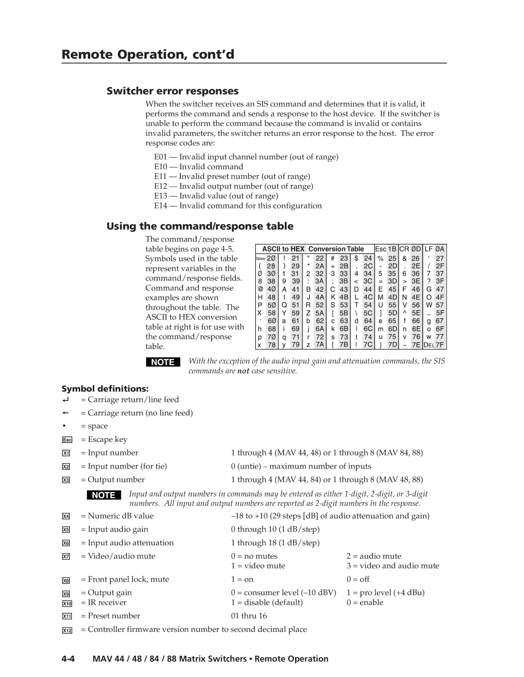
The command/response table begins on page
ASCII to HEX Conversion Table
Space |
With the exception of the audio input gain and attenuation commands, the SIS commands are not case sensitive.
Symbol definitions:
= Carriage return/line feed
= Carriage return (no line feed)
•= space
Esc
X1
X2
X3
X4
X5
X6
X7
X8
X9
X10
X11
X12
= Escape key |
|
= Input number | 1 through 4 (MAV 44, 48) or 1 through 8 (MAV 84, 88) |
= Input number (for tie) | 0 (untie) – maximum number of inputs |
= Output number | 1 through 4 (MAV 44, 84) or 1 through 8 (MAV 48, 88) |
Input and output numbers in commands may be entered as either
= Numeric dB value | ||||
= Input audio gain | 0 through 10 (1 dB/step) |
|
| |
= Input audio attenuation | 1 through 18 (1 dB/step) |
|
| |
= Video/audio mute | 0 | = no mutes | 2 | = audio mute |
| 1 | = video mute | 3 | = video and audio mute |
= Front panel lock, mute | 1 | = on | 0 | = off |
= Output gain | 0 = consumer level | 1 | = pro level (+4 dBu) | |
= IR receiver | 1 | = disable (default) | 0 = enable | |
= Preset number | 01 thru 16 |
|
| |
= Controller firmware version number to second decimal place