Installation, cont’d
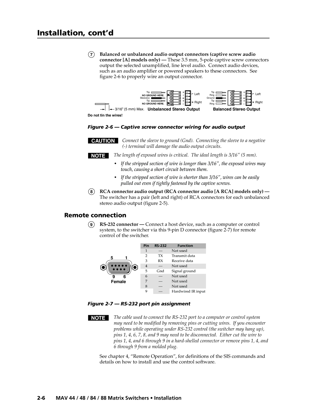
7Balanced or unbalanced audio output connectors (captive screw audio connector [A] models only) — These 3.5 mm,
Tip | L | Left | Tip | L | Left | |
NO GROUND HERE. | Ring | |||||
|
|
|
| |||
Sleeve(s) |
|
| Ground |
|
| |
Tip | R | Right | Tip | R | Right | |
NO GROUND HERE. | Ring | |||||
|
|
|
|
3/16” (5 mm) Max. Unbalanced Stereo Output | Balanced Stereo Output |
Do not tin the wires!
Figure 2-6 — Captive screw connector wiring for audio output
CAUTION
Connect the sleeve to ground (Gnd). Connecting the sleeve to a negative
The length of exposed wires is critical. The ideal length is 3/16” (5 mm).
•If the stripped section of wire is longer than 3/16”, the exposed wires may touch, causing a short circuit between them.
•If the stripped section of wire is shorter than 3/16”, wires can be easily pulled out even if tightly fastened by the captive screws.
8RCA connector audio output (RCA connector audio [A RCA] models only) — The switcher has a pair (left and right) of RCA connectors for each unbalanced stereo audio output (figure
Remote connection
9
|
| Pin | Function | ||
|
| 1 | — | Not used | |
5 | 1 | 2 | TX | Transmit data | |
3 | RX | Receive data | |||
|
| ||||
|
| 4 | — | Not used | |
|
| 5 | Gnd | Signal ground | |
9 | 6 | 6 | — | Not used | |
Female | 7 | — | Not used | ||
|
| 8 | — | Not used | |
|
| 9 | — | Hardwired IR input | |
Figure 2-7 — RS-232 port pin assignment
The cable used to connect the
See chapter 4, “Remote Operation”, for definitions of the SIS commands and details on how to install and use the control software.