Installation, cont’d
Control connections
The MKP has two
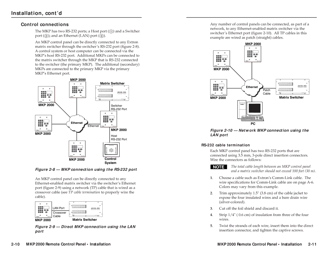
Any number of control panels can be connected, as part of a network, to any
An MKP control panel can be directly connected to any Extron matrix switcher through the switcher’s
1 2 3
4 5 6
7 8 9
BACK 0
MKP 2000
MKP 2000
MKP 2000
1 2 3
4 5 6
7 8 9
BACK 0
MKP 2000
1 2 3
4 5 6
7 8 9
BACK 0
MKP 2000
MKP 2000 |
| Matrix Switcher |
|
|
|
|
|
|
|
|
|
|
|
|
|
|
|
| ||||||||||||
|
|
|
|
|
|
|
| 13 | 14 | 15 | 16 | 17 | 18 | 19 | 20 | 21 | 22 | 23 | 24 | |||||||||||
|
|
|
|
|
|
|
|
|
|
|
|
|
|
| 1 | 2 | 3 |
| 1 | 2 | 3 | 4 | 5 | 6 | 7 | 8 | 9 | 10 | 11 | 12 |
4 | 5 | 6 |
|
|
|
|
|
|
|
|
|
|
|
| 4 | 5 | 6 | Ethernet |
|
|
|
|
|
|
|
|
|
|
|
|
1 | 2 | 3 |
|
|
|
|
|
|
|
|
|
|
|
|
|
|
|
|
|
|
|
|
|
|
|
|
|
|
|
|
|
|
|
|
|
|
|
|
|
|
|
|
|
|
| 7 | 8 | 9 |
|
|
|
|
|
|
|
|
|
|
|
|
|
BACK 0 |
| 13 | 14 | 15 | 16 | 17 | 18 | 19 | 20 | 21 | 22 | 23 | 24 | BACK 0 |
| Patch | 1 | 2 | 3 | 4 | 5 | 6 | 7 | 8 | 9 | 10 | 11 | 12 | ||
7 | 8 | 9 | 1 | 2 | 3 | 4 | 5 | 6 | 7 | 8 | 9 | 10 | 11 | 12 |
|
|
|
|
|
|
|
|
|
|
|
|
|
|
|
|
|
|
|
|
|
|
|
|
|
|
|
|
|
|
|
|
|
|
| 13 | 14 | 15 | 16 | 17 | 18 | 19 | 20 | 21 | 22 | 23 | 24 |
|
|
| 1 | 2 | 3 | 4 | 5 | 6 | 7 | 8 | 9 | 10 | 11 | 12 |
|
| MKP 2000 | Cable |
|
|
|
|
|
|
|
|
|
|
|
|
MKP 2000 | 13 | 14 | 15 | 16 | 17 | 18 | 19 | 20 | 21 | 22 | 23 | 24 | MKP 2000 | Matrix Switcher |
MKP 2000
1 2 3
4 5 6
7 8 9
BACK 0
MKP 2000
MKP 2000
Ethernet
Ethernet
Switcher
1 2 3
4 5 6
7 8 9
BACK 0
MKP 2000
MKP 2000
Host
PC
Figure 2-10 — Network MKP connection using the LAN port
1 | 2 | 3 |
4 | 5 | 6 |
7 | 8 | 9 |
BACK | 0 |
|
MKP 2000 |
|
MKP 2000 | Control |
| System |
RS-232 cable termination
Each MKP control panel has two
Figure 2-8 — MKP connection using the RS-232 port
An MKP control panel can be directly connected to any
1 | 2 | 3 |
| 1 | 2 | 3 | 4 | 5 | 6 | 7 | 8 | 9 | 10 | 11 | 12 |
7 | 8 | 9 | LAN Port | 13 | 14 | 15 | 16 | 17 | 18 | 19 | 20 | 21 | 22 | 23 | 24 |
4 | 5 | 6 |
|
|
|
|
|
|
|
|
|
|
|
|
|
BACK 0 |
| Crossover | 1 | 2 | 3 | 4 | 5 | 6 | 7 | 8 | 9 | 10 | 11 | 12 | |
|
|
| 13 | 14 | 15 | 16 | 17 | 18 | 19 | 20 | 21 | 22 | 23 | 24 | |
|
| MKP 2000 | Cable |
|
|
|
|
|
|
|
|
|
|
|
|
MKP 2000 |
| Matrix Switcher | |||||||||||||
Figure 2-9 — Direct MKP connection using the LAN port
|
| The total cable length between an MKP control panel |
|
| and a matrix switcher should not exceed 100 feet (30 m). |
1. | Choose a cable such as Extron’s | |
| wire specifications for | |
| Colors may vary from this example. | |
2. | Trim approximately 1.5" (3.8 cm) of the cable jacket to | |
| expose the four insulated wires and a bare drain wire | |
| ||
3. | Cut off the foil shield and discard it. | |
4. | Strip 1/4" ( 0.6 cm) of insulation from three of the four | |
| wires. | |
5. | Twist the strands of each wire, insert them into the direct | |
| insertion connector, and tighten the captive screws. | |
MKP 2000 Remote Control Panel • Installation |