Installation, cont’d
Power supply wiring
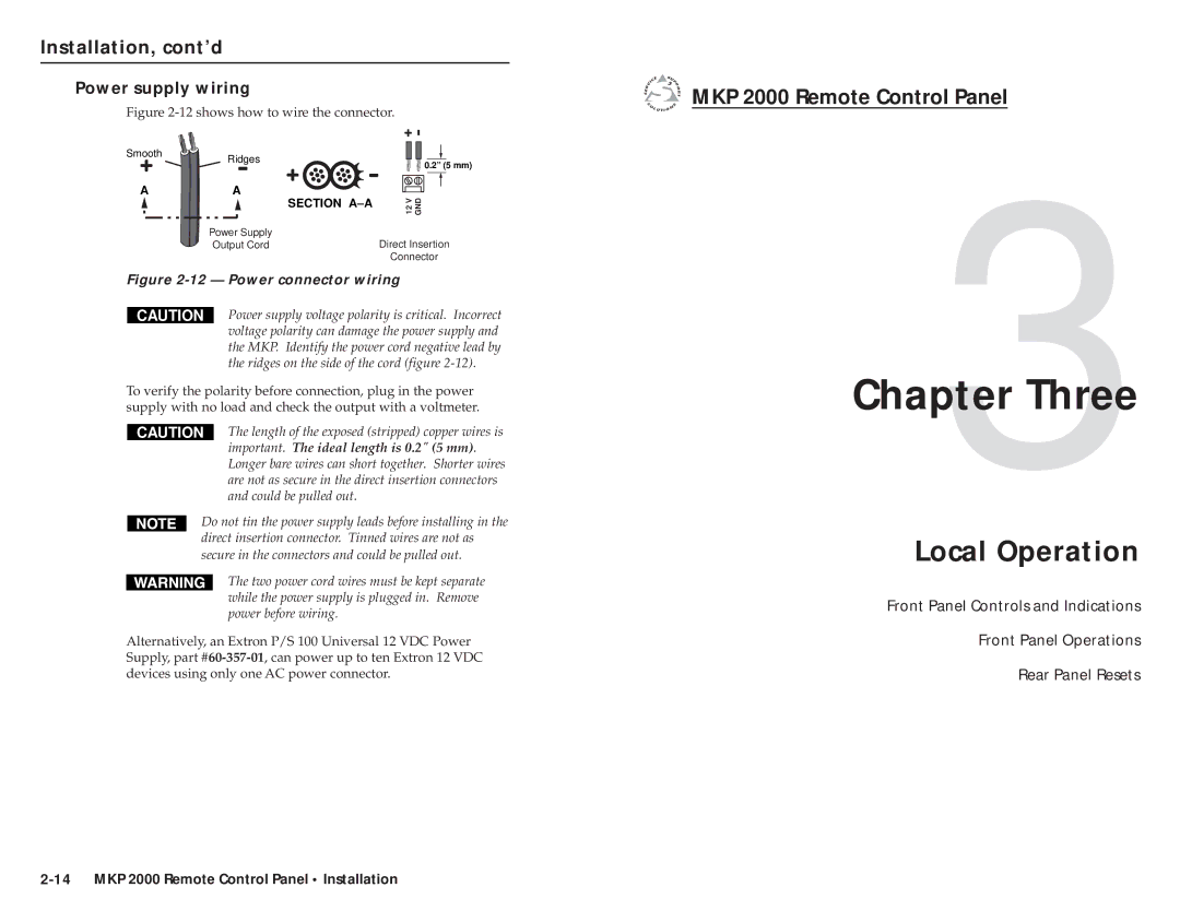
Figure 2-12 shows how to wire the connector.
Smooth | Ridges |
| 0.2” (5 mm) |
| A |
| A |
|
|
|
|
|
|
|
|
|
|
|
|
|
| SECTION |
|
|
|
|
|
|
|
| |||||
|
| 12V GND | |||||||||||||
|
|
|
|
|
| ||||||||||
|
|
|
|
|
|
|
|
|
|
|
| ||||
|
| Power Supply |
|
|
|
|
|
|
|
|
|
|
|
| |
|
| Output Cord |
|
|
|
| Direct Insertion | ||||||||
|
|
|
|
|
|
|
| Connector | |||||||
Figure | |||||||||||||||
|
|
| Power supply voltage polarity is critical. Incorrect | ||||||||||||
| CAUTION |
| |||||||||||||
|
|
| voltage polarity can damage the power supply and | ||||||||||||
the MKP. Identify the power cord negative lead by the ridges on the side of the cord (figure
To verify the polarity before connection, plug in the power supply with no load and check the output with a voltmeter.
CAUTION | The length of the exposed (stripped) copper wires is |
| important. The ideal length is 0.2" (5 mm). |
| Longer bare wires can short together. Shorter wires |
| are not as secure in the direct insertion connectors |
| and could be pulled out. |
Do not tin the power supply leads before installing in the direct insertion connector. Tinned wires are not as secure in the connectors and could be pulled out.
The two power cord wires must be kept separate while the power supply is plugged in. Remove power before wiring.
Alternatively, an Extron P/S 100 Universal 12 VDC Power Supply, part

 MKP 2000 Remote Control Panel
Chapter3Three
Local Operation
Front Panel Controls and Indications
Front Panel Operations
Rear Panel Resets