Installation, cont’d
Preparing the site, installing the mud ring or wall box
Choose a location that allows cable runs without interference. Allow enough depth for both the wall box and the cables. You may need to install the cables into the wall, furniture, or conduits before installing the control panel.
The installation must conform to national and local electrical codes and to the equipment’s size requirements. An
Installation using a UL listed wall box (available from Extron) is recommended for most mounting options, but the included mud rings can be used instead.
Before using the mud rings, verify that the installation conforms to national and local electrical codes.
CAUTION | Extron provides one mud ring with each MKP |
| control panel. However, the user may choose to |
| use a wall box. Because the tolerances on electrical |
| boxes are very loose, it is recommended that you |
| measure the actual box that you plan to use before |
| making any precise cuts. |
The electrical box must be at least 2.5" (7 cm) deep to accommodate the MKP’s rear enclosure.
Install the mud ring or wall box as follows:
1a. | If you are using a mud ring, use the template that came | |
| with the mud ring. Cut out the indicated center portion. | |
|
| To meet the UL listing requirements, this device must be |
|
| |
|
| installed in a wall box. |
1b. | If you are using a wall box, cut out or make a 100% size | |
| photocopy of the | |
| corresponds to the faceplate you are using, and cut out the | |
| center portion of it as indicated on the template. | |
2. | Place the template (or the wall box or mud ring) against | |
| the installation surface, and mark the guidelines for the | |
| opening on the wall or furniture. | |
3. | Cut out the wall/furniture material from the marked area. | |
4. | Check the opening size by inserting the wall box, mud | |
| ring, or control panel into the opening. The box or mud | |
ring (if used) and/or control panel should fit easily into the opening. Enlarge or smooth the edges of the opening if needed.
5. If you are using a wall box, feed cables through the wall box
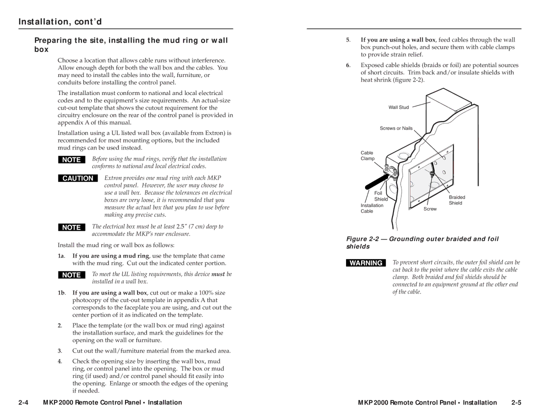
6. | Exposed cable shields (braids or foil) are potential sources | ||
| of short circuits. Trim back and/or insulate shields with | ||
| heat shrink (figure |
| |
| Wall Stud |
|
|
| Screws or Nails |
|
|
| Cable |
|
|
| Clamp |
|
|
| Foil |
| Braided |
| Shield |
| |
|
| Shield | |
| Installation |
| |
| Screw |
| |
| Cable |
| |
|
|
| |
Figure 2-2 — Grounding outer braided and foil shields
To prevent short circuits, the outer foil shield can be cut back to the point where the cable exits the cable clamp. Both braided and foil shields should be connected to an equipment ground at the other end of the cable.
MKP 2000 Remote Control Panel • Installation | MKP 2000 Remote Control Panel • Installation |