Installation
Rear Panel Features and Cabling
2 | 3 | 4 | 10 |
RGBVIDEO
1A | 2A | 3 |
|
|
| I |
|
|
| N |
POWER | P | ||
U | |||
|
|
| T |
|
|
| S |
|
|
|
|
12V | 1B | 2B | 4 |
3A MAX |
|
|
|
1
RGB
O
U
T
P
U
T
S
VIDEO
5
|
| LISTED 17TT |
|
| AMPLIFIED OUTPUTS | |
|
|
|
|
|
| |
® | US AUDIO/VIDEO |
|
|
| 4/8 | |
|
| APPARATUS |
|
|
| |
|
|
|
|
| Ohms | |
|
|
|
|
|
| |
|
|
|
|
| L | R |
| ON | STEREO | AUX/MIX IN | DC VOL | ||
HIGH | Tx Rx IR | 12V | ||||
ON |
|
|
|
| ||
PASS |
|
|
|
|
|
|
FILTER |
|
| A B C |
|
| |
| OFF | DUAL |
|
| 10V | |
| MONO |
|
|
| VOL/MUTE | |
|
|
|
|
| ||
6 | 7 | 8 | 9 |
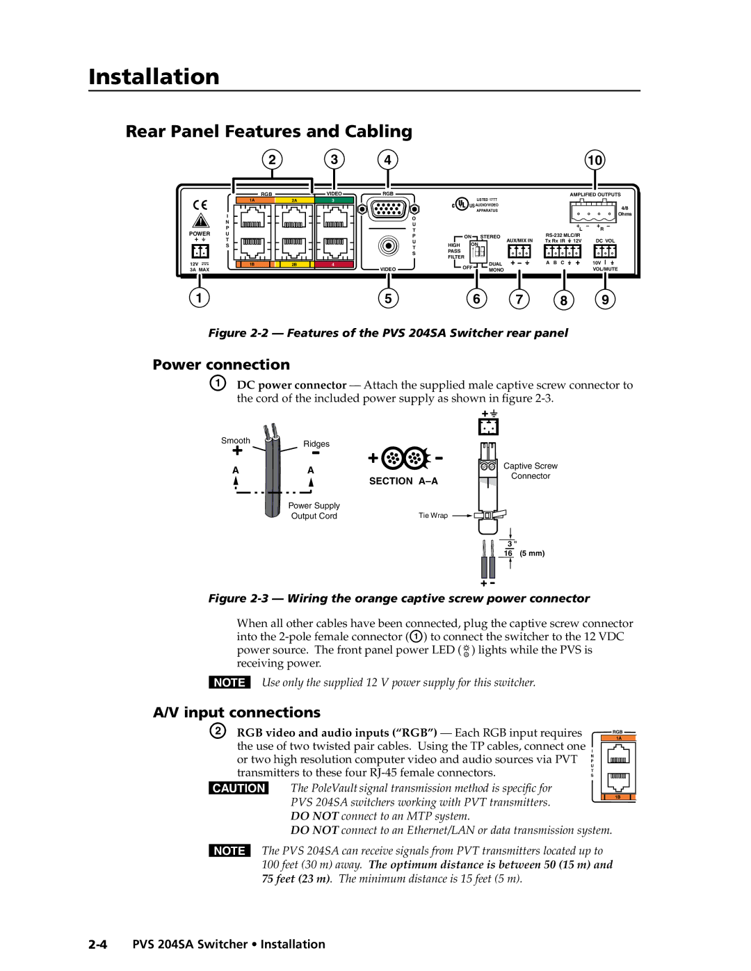
Figure 2-2 — Features of the PVS 204SA Switcher rear panel
Power connection
A DC power connector — Attach the supplied male captive screw connector to the cord of the included power supply as shown in figure
PRELIMINARY
Smooth | Ridges |
| |
A | A |
SECTION
Power Supply |
|
Output Cord | Tie Wrap |
Captive Screw
Connector
3 "
16 (5 mm)
Figure 2-3 — Wiring the orange captive screw power connector
When all other cables have been connected, plug the captive screw connector into the ![]() ) lights while the PVS is receiving power.
) lights while the PVS is receiving power.
NUse only the supplied 12 V power supply for this switcher.
A/V input connections
BB RGB video and audio inputs (“RGB”) — Each RGB input requires |
|
|
|
| 1A | |
|
|
|
| RGB | ||
the use of two twisted pair cables. Using the TP cables, connect one | I | |||||
or two high resolution computer video and audio sources via PVT | N | |||||
| P |
|
|
| ||
transmitters to these four | U | |||||
S | ||||||
| T | |||||
CThe PoleVault signal transmission method is specific for
PVS 204SA switchers working with PVT transmitters. |
| 1B |
|
|
|
|
DO NOT connect to an MTP system.
DO NOT connect to an Ethernet/LAN or data transmission system.
NThe PVS 204SA can receive signals from PVT transmitters located up to 100 feet (30 m) away. The optimum distance is between 50 (15 m) and 75 feet (23 m). The minimum distance is 15 feet (5 m).