N
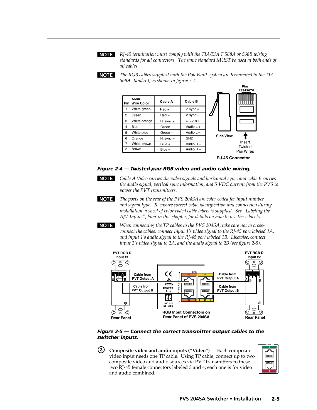
NThe RGB cables supplied with the PoleVault system are terminated to the TIA 568A standard, as shown in figure
Pins:
12 3 4 5 6 7 8
| 568A | Cable A | Cable B |
|
|
|
|
Pin | Wire Color |
|
|
|
| ||
|
|
|
|
|
|
|
|
1 | Red + | V. sync + |
|
|
|
| |
|
|
|
|
|
|
|
|
2 | Green | Red – | V. sync – |
|
|
|
|
|
|
|
| ||||
|
|
|
|
|
|
|
|
3 | H. sync + | + 5 VDC |
|
|
|
| |
|
|
|
| ||||
4 | Blue | Green + | Audio L + |
|
|
|
|
|
|
|
|
|
|
|
|
5 | Green – | Audio L – |
|
|
|
| |
Side View |
| ||||||
|
|
|
|
| |||
6 | Orange | H. sync – | GND |
| |||
|
| Insert |
| ||||
|
|
|
|
|
|
| |
7 | Blue + | Audio R + |
| ||||
|
| Twisted |
| ||||
8 | Brown | Blue – | Audio R – |
|
|
| |
Pair Wires |
| ||||||
|
|
|
|
| |||
|
|
|
|
| |||
|
|
|
|
| |||
Figure 2-4 — Twisted pair RGB video and audio cable wiring.
NCable A Video carries the video signals and horizontal sync, and cable B carries the audio signal, vertical sync information, and 5 VDC current from the PVS to power the PVT transmitters.
NThe ports on the rear of the PVS 204SA are color coded for input number and signal type. To ensure correct cable identification and connection during installation, a sheet of color coded cable labels is supplied. See “Labeling the A/V Inputs”, later in this chapter, for details on how to use these labels.
NWhen connecting the TP cables to the PVS 204SA, take care not to cross- connect the cables; connect input 1’s video signal to the
PVT RGB D | PVT RGB D |
Input #1 | Input #2 |
|
| Cable from |
|
| RGB |
|
|
| 1A | 2A | |
A | B | PVT Output A |
| I |
|
|
|
| |||
|
| Cable from |
| N |
|
|
|
| P |
| |
|
| PVT Output B | POWER | U |
|
|
|
| T |
| |
|
|
|
| S |
|
|
|
|
| 1B | 2B |
|
|
| 12V |
|
|
|
|
| 3A MAX |
|
|
|
|
| RGB Input Connectors on | ||
Rear Panel |
| Rear Panel of PVS 204SA | |||
Cable from |
|
|
PVT Output A | A | B |
| ||
|
|
Cable from
PVT Output B
Rear Panel
Figure 2-5 — Connect the correct transmitter output cables to the switcher inputs.
C | Composite video and audio inputs (”Video”) — Each composite |
| video input needs one TP cable. Using TP cable, connect up to two |
| composite video and audio sources via PVT transmitters to these |
| two |
| and audio combined. |
VIDEO
3
4
PVS 204SA Switcher • Installation |