F | Min/Max LED — This red LED indicates when the range limits for the power |
| amplifier level, Aux/Mix volume, or input gain level have been reached. See |
| “Setting Up and Optimizing the Audio”, later in this chapter, for details. |
| It lights as follows: |
•When setting up input levels
•When the PVS reaches the min./max. amplifier level
•When the PVS reaches the min./max. Aux/Mix level
G | Aux/Mix level encoder — This recessed rotary encoder allows front panel |
| adjustments specific to the Aux/Mix input level. The encoder has 16 positions |
| per revolution, with each position equivalent to a 1 dB step |
| range). |
H | Power amp level adjustment encoder (“Level”) — This recessed rotary |
| encoder allows front panel adjustment to all inputs (global) or, when used in |
| conjunction with any selected input button, allows individual channel gain |
| adjustment. The encoder has 16 positions per revolution, with each position |
| equivalent to a 1 dB step |
I Clip LED — This red LED lights when the output amplifier is clipping.
NTo reduce the risk of damaging equipment, turn the power amp level down (counterclockwise) when this LED is lit.
Setting Switcher Modes
The PVS 204SA has two selectable switcher modes: single switcher and separate switcher. The default setting is single switcher mode.
Single switcher mode
This mode makes the PVS function as a 4x1 switcher. In single switcher mode, the RGB video output is inactive when composite video input is selected, and the composite video output is inactive when RGB video input is selected. Either RGB video OR composite video is output to the projector or display device, depending on which signal format is selected.
NThe switcher should be set to single switcher mode if an MLC is connected.
Separate switcher mode
In this mode, both signal formats (RGB and composite video) are active at the same time, allowing RGB video AND composite video to be output to the projector or display device. The two modes can be toggled by front panel or
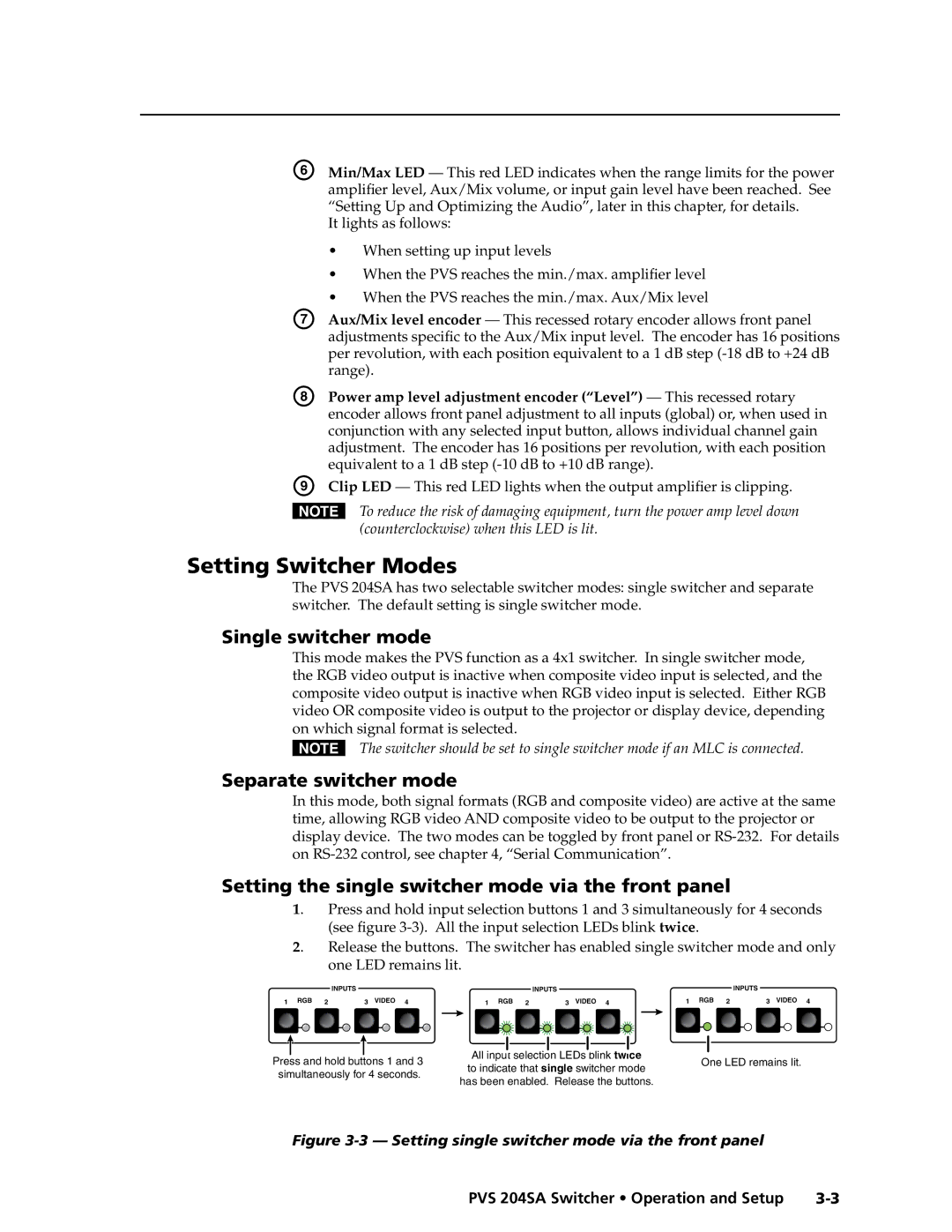
Setting the single switcher mode via the front panel
1. Press and hold input selection buttons 1 and 3 simultaneously for 4 seconds (see figure
2. |
|
| Release the buttons. The switcher has enabled single switcher mode and only | ||||||||||||||||||||||||||||||||
|
|
|
| one LED remains lit. |
|
|
|
|
|
|
|
|
|
|
|
|
|
|
|
|
|
|
|
|
|
|
| ||||||||
|
|
|
| INPUTS |
|
|
|
| INPUTS |
|
|
|
|
|
| INPUTS | |||||||||||||||||||
1 RGB | 2 |
|
| 3 VIDEO 4 | 1 RGB 2 |
|
| 3 VIDEO 4 |
|
|
| 1 RGB 2 |
|
| 3 VIDEO 4 | ||||||||||||||||||||
|
|
|
|
|
|
|
|
|
|
|
|
|
|
|
|
|
|
|
|
|
|
|
|
|
|
|
|
|
|
|
|
|
|
|
|
|
|
|
|
|
|
|
|
|
|
|
|
|
|
|
|
|
|
|
|
|
|
|
|
|
|
|
|
|
|
|
|
|
|
|
|
Press and hold buttons 1 and 3 | All input selection LEDs blink twice | One LED remains lit. | |
to indicate that single switcher mode | |||
simultaneously for 4 seconds. |
| ||
has been enabled. Release the buttons. |
| ||
|
|
Figure 3-3 — Setting single switcher mode via the front panel
PVS 204SA Switcher • Operation and Setup |
PRELIMINARY