PVS 204SA Switcher’s |
|
| RGB | VIDEO | RGB |
|
|
| AMPLIFIED OUTPUTS | ||
rear panel |
| 1A | 2A | 3 |
|
| LISTED 17TT |
|
| 4/8 Ohms | |
|
|
|
|
|
| US AUDIO/VIDEO | DO NOT GROUND |
|
| ||
| I |
|
|
|
| APPARATUS | OR SHORT |
|
| ||
Tx Rx IR | +12V |
|
|
| O |
|
| SPEAKER OUTPUTS! |
|
| |
| N |
|
| U | ON | STEREO |
| L | R | ||
POWER | P |
|
| T |
| ||||||
U |
|
|
|
|
| ||||||
|
|
| T |
|
| P | HIGH |
| DC VOL | ||
|
|
|
|
| U | PASS |
| Tx Rx IR | 12V | ||
|
|
| S |
|
| T |
|
|
|
| |
|
|
|
|
|
| FILTER |
|
|
|
| |
|
|
|
|
|
| S |
|
|
|
|
|
|
| 12V | 1B | 2B | 4 |
| OFF | DUAL | AUX/MIX IN A B C |
| 10V |
|
|
|
| MONO |
| ||||||
|
| 3A MAX |
|
|
| VIDEO |
|
|
|
| VOL/MUTE |
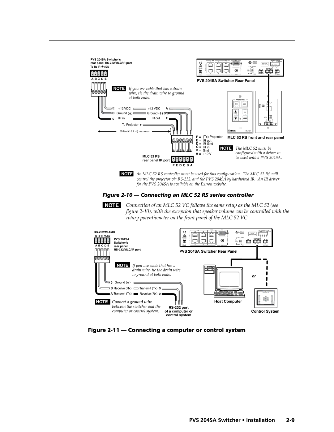
A B C D E | PVS 204SA Switcher Rear Panel |
|
|
| |||||||
|
|
|
|
| |||||||
NOTE If you use cable that has a drain |
|
| |||
| wire, tie the drain wire to ground |
|
| ||
| at both ends. |
| PROJECTOR | ||
|
|
|
| ON OFF | |
E | +12 VDC | +12 VDC | A |
|
|
D | Ground ( ) | Ground ( | ) B/D | VOL | PC |
|
|
|
|
| |
C | IR in | IR out | E | VOL | VIDEO |
| |||||
|
|
|
|
| Tx IR OUT GND IR IN GND + 12V |
| To Projector F |
|
|
|
|
| 50 feet (15.2 m) maximum |
|
| MLC 52 | |
MLC 52 RS
rear panel IR port
F E D C B A |
F=
E = D = C = B = A =
(Tx) Projector | MLC 52 RS front and rear panel |
IR out |
|
IR Gnd |
|
IR in | NOTE The MLC 52 must be |
Gnd | configured with a driver to |
+12 V | |
| be used with a PVS 204SA. |
NOTE An MLC 52 RS controller must be used for this configuration. The MLC 52 RS will control the projector via
Figure 2-10 — Connecting an MLC 52 RS series controller
NConnection of an MLC 52 VC follows the same setup as the MLC 52 (see figure
Tx Rx IR +12V | PVS 204SA |
| |
A B C D E | Switcher’s |
rear panel | |
|
|
|
| RGB | VIDEO | RGB |
|
|
|
|
|
| AMPLIFIED OUTPUTS | |
| 1A | 2A | 3 |
|
|
| LISTED 17TT |
|
|
|
| 4/8 Ohms |
|
|
|
|
|
| US AUDIO/VIDEO | DO NOT GROUND |
|
|
| ||
| I |
|
|
|
|
| APPARATUS | OR SHORT |
|
|
| |
|
|
|
| O |
|
| SPEAKER OUTPUTS! |
|
|
| ||
| N |
|
|
| U |
|
|
|
|
|
|
|
POWER | P |
|
|
| T | ON | STEREO |
|
|
| L | R |
U |
|
|
| P |
|
|
|
| ||||
| T |
|
|
| U | HIGH |
|
| Tx Rx IR | 12V | DC VOL | |
| S |
|
|
| T | PASS |
|
|
|
|
|
|
|
|
|
|
| S | FILTER |
|
|
|
|
|
|
12V | 1B | 2B | 4 | VIDEO |
| OFF | DUAL | AUX/MIX IN | A B | C |
| 10V |
3A MAX |
|
|
|
|
| MONO |
|
|
|
| VOL/MUTE | |
PVS 204SA Switcher Rear Panel
NOTE If you use cable that has a |
|
drain wire, tie the drain wire |
|
to ground at both ends. | or |
| |
Ground ( ) |
|
B Receive (Rx) | Transmit (Tx) | 3 |
A Transmit (Tx) | Receive (Rx) | 2 |
NOTE Connect a ground wire between the switcher and the computer or control system.
Host Computer
of a computer orControl System control system
Figure 2-11 — Connecting a computer or control system
PVS 204SA Switcher • Installation |