Labeling the A/V Inputs
Labeling and connecting the A/V input cables
The RGB and composite video input ports on the rear of the PVS 204SA are color
coded to aid easy identification of the input signal type. A sheet of corresponding colored labels is supplied for the installer to label the cables running from the PVT transmitters to the switcher. Once the labels are attached to the cables, the signal type transmitted on any cable can clearly be identified, enabling correct cable connection during installation.
To label the cables,
1. | Peel off the label corresponding to the cable’s signal type (see the table below) |
| and affix it close to one end of the cable. |
NAlign and press the colored section of the label to the cable first, then wrap the clear section around the cable, allowing the signal type name to be easily read.
RGB #1A
Figure 2-17 — Wrap the label around the cable, colored part first.
2.
3.
4.
Repeat step 1 for the other end of the cable, using the same label type.
Using the correct label type, repeat steps 1 and 2 as necessary for all signal cables that are to be connected to the PVS 204SA.
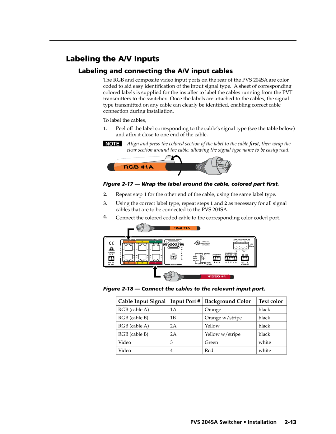
Connect the colored coded cable to the corresponding color coded port.
RGB #1A
| I |
| N |
POWER | P |
U | |
| T |
| S |
12V |
|
3A MAX |
|
RGBVIDEO
1A | 2A | 33 |
1B | 2B | 44 |
RGB
O
U
T
P
U
T
S
VIDEO
|
| LISTED 17TT |
|
| AMPLIFIED OUTPUTS | |
|
|
|
|
|
| |
® | US AUDIO/VIDEO |
|
|
| 4/8 | |
|
| APPARATUS |
|
|
| |
|
|
|
|
| Ohms | |
|
|
|
|
|
| |
|
|
|
|
| L | R |
| ON | STEREO | AUX/MIX IN | DC VOL | ||
HIGH | ON | Tx Rx IR | 12V | |||
|
|
|
| |||
PASS |
|
|
|
|
|
|
FILTER |
|
|
|
|
| |
| OFF | DUAL |
| A B C |
| 10V |
| MONO |
|
|
| VOL/MUTE | |
|
|
|
|
| ||
VIDEO #4
Figure 2-18 — Connect the cables to the relevant input port.
Cable Input Signal | Input Port # | Background Color | Text color |
RGB (cable A) | 1A | Orange | black |
RGB (cable B) | 1B | Orange w/stripe | black |
|
|
|
|
RGB (cable A) | 2A | Yellow | black |
|
|
|
|
RGB (cable B) | 2A | Yellow w/stripe | black |
|
|
|
|
Video | 3 | Green | white |
|
|
|
|
Video | 4 | Red | white |