Error responses
When the PVS switcher receives a valid SIS command, it executes the command and sends a response to the host device. If the PVS is unable to execute the command because the command is invalid or it contains invalid parameters, it returns an error response to the host.
The error response codes and their descriptions are as follows:
E01 – Invalid input channel number (too large)
E06 – Invalid channel change
E10 – Invalid command
E13 – Invalid value (too large)
E14 – Invalid command for this configuration
Using the command/response tables
The command/response tables in this chapter list valid command ASCII codes, the PVS’s responses to the host, and a description of the command’s function or the results of executing the command. Upper and lower case characters may be used interchangeably in the command field unless otherwise specified (setting gain/ attenuation, for example).
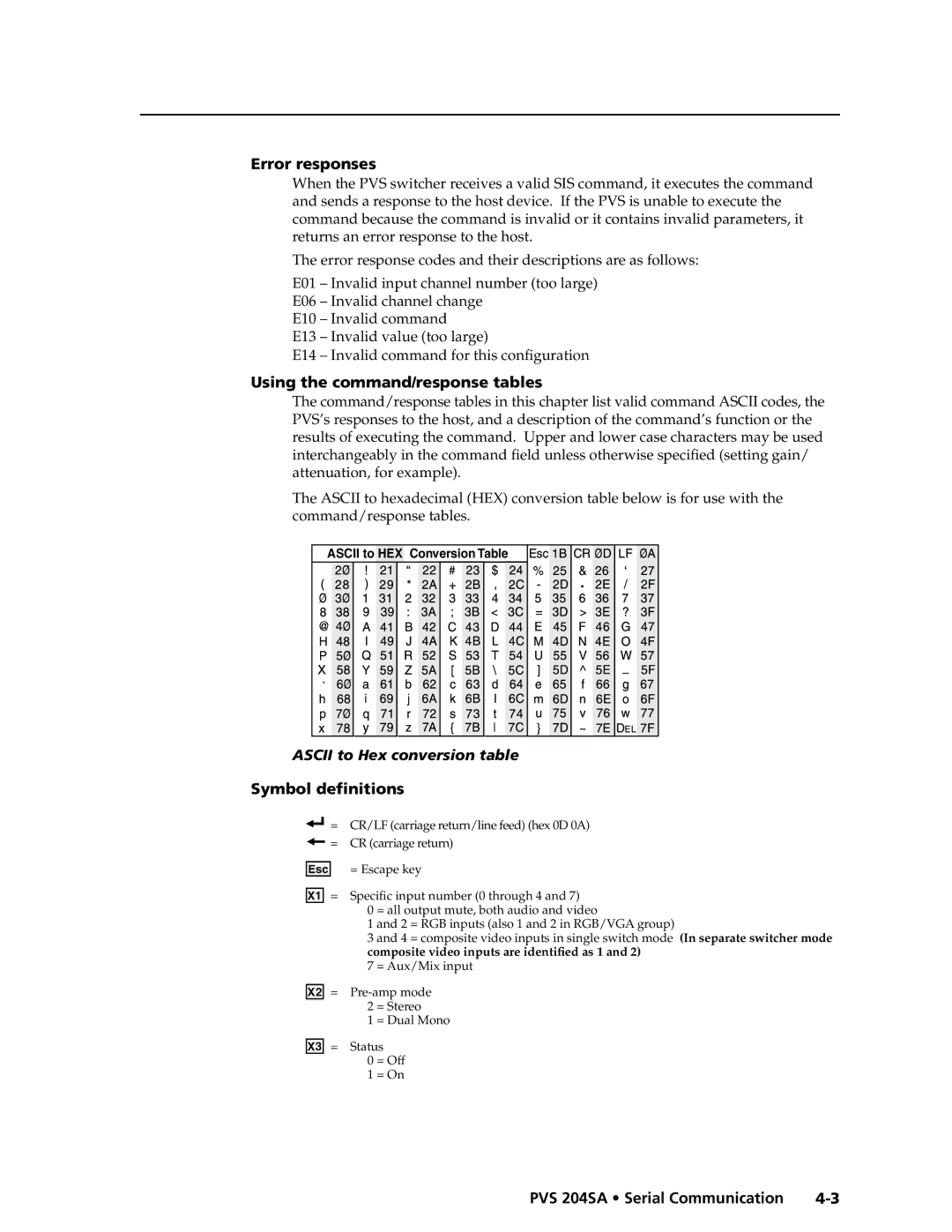
The ASCII to hexadecimal (HEX) conversion table below is for use with the
command/response tables.
ASCII to HEX Conversion Table |
• |
ASCII to Hex conversion table
Symbol definitions
] = CR/LF (carriage return/line feed) (hex 0D 0A)
}= CR (carriage return)
E = Escape key
X! = Specific input number (0 through 4 and 7)
0 = all output mute, both audio and video
1 and 2 = RGB inputs (also 1 and 2 in RGB/VGA group)
3 and 4 = composite video inputs in single switch mode (In separate switcher mode
composite video inputs are identified as 1 and 2) 7 = Aux/Mix input
X@ =
1 = Dual Mono X# = Status
0 = Off
1 = On
PRELIMINARY
PVS 204SA • Serial Communication |