Installation, cont’d
N
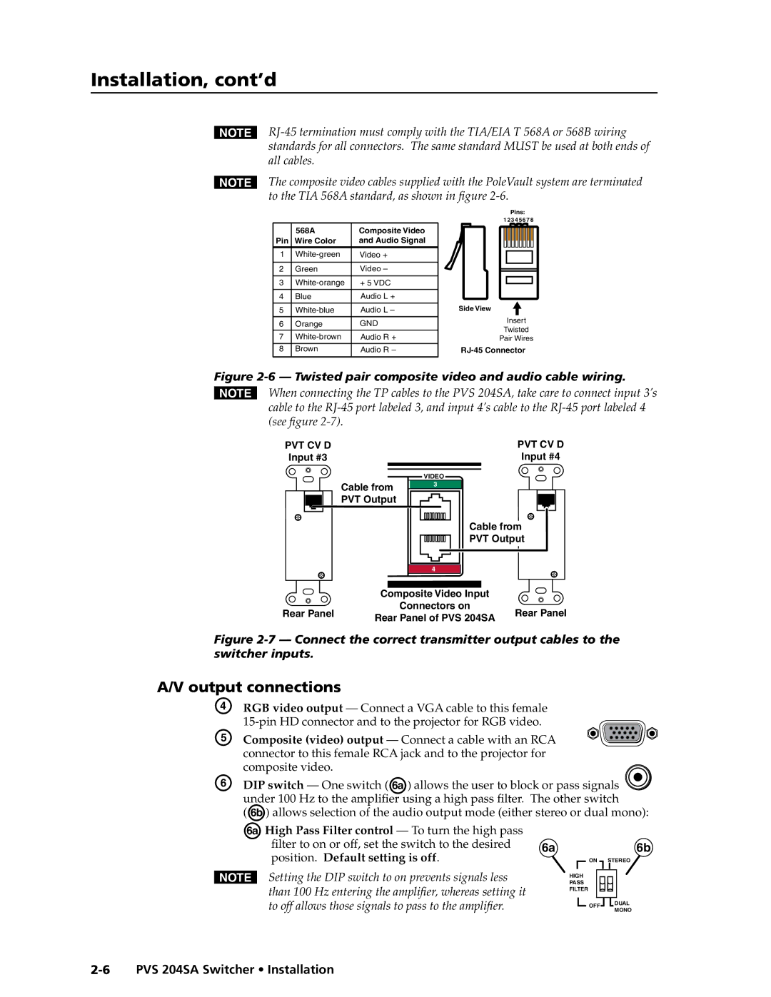
NThe composite video cables supplied with the PoleVault system are terminated to the TIA 568A standard, as shown in figure
Pins:
1 2 3 4 5 6 7 8
| 568A | Composite Video |
|
|
|
|
|
|
|
|
| ||
Pin | Wire Color | and Audio Signal |
|
|
|
|
|
|
|
| |||
1 | Video + |
|
|
|
| |
|
|
|
| |||
|
|
|
|
|
|
|
2 | Green | Video – |
|
|
|
|
|
|
|
|
|
|
|
3 | + 5 VDC |
|
|
|
| |
|
|
|
| |||
|
|
|
|
|
|
|
4 | Blue | Audio L + |
|
|
|
|
|
|
| Side View |
| ||
5 | Audio L – |
| ||||
|
|
|
|
| Insert |
|
6 | Orange | GND |
| |||
|
| Twisted |
| |||
7 | Audio R + |
|
|
| ||
Pair Wires |
| |||||
8 | Brown | Audio R – |
| |||
Figure 2-6 — Twisted pair composite video and audio cable wiring.
NWhen connecting the TP cables to the PVS 204SA, take care to connect input 3’s cable to the
PRELIMINARY
PVT CV D
Input #3
Rear Panel
|
| PVT CV D | |
|
| Input #4 | |
| VIDEO |
| |
Cable from | 3 |
| |
|
| ||
PVT Output |
|
| |
| Cable from | ||
| PVT Output | ||
| 4 |
| |
Composite Video Input |
| ||
| Connectors on | Rear Panel | |
Rear Panel of PVS 204SA | |||
| |||
Figure 2-7 — Connect the correct transmitter output cables to the switcher inputs.
A/V output connections
D | RGB video output — Connect a VGA cable to this female |
|
| |
E |
|
| ||
Composite (video) output — Connect a cable with an RCA |
|
| ||
| connector to this female RCA jack and to the projector for |
|
| |
F | composite video. |
|
|
|
DIP switch — One switch (Ä) allows the user to block or pass signals | ||||
| under 100 Hz to the amplifier using a high pass filter. The other switch | |||
| (Ã) allows selection of the audio output mode (either stereo or dual mono): | |||
| ÄHigh Pass Filter control — To turn the high pass |
|
|
|
| filter to on or off, set the switch to the desired | 6a |
| 6b |
| position. Default setting is off. |
| ON STEREO | |
N Setting the DIP switch to on prevents signals less |
| HIGH |
| |
| PASS |
| ||
| than 100 Hz entering the amplifier, whereas setting it |
| FILTER |
|
|
|
|
| |
| to off allows those signals to pass to the amplifier. |
| OFF | DUAL |
|
| MONO | ||
|
|
| ||