PRELIMINARY
Operation and Setup
Front Panel Features and Operation
PVS 204SA
|
|
|
|
|
|
| POLEVAULT SWITCHER |
AUTOSW | LOCKOUT |
|
| INPUTS |
| AUDIO | |
1 | RGB 2 | 3 VIDEO 4 | CONFIG | AUX/MIX | LEVEL | ||
|
|
|
|
|
| ||
|
|
|
|
|
| MIN/MAX | CLIP |
1 | 2 | 3 | 4 | 5 | 6 | 7 | 8 | 9 |
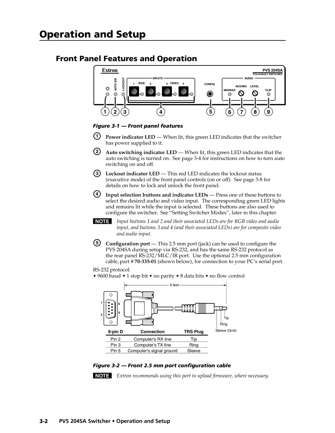
Figure 3-1 — Front panel features
A
B Auto switching indicator LED — When lit, this green LED indicates that the auto switching is turned on. See page
C | Lockout indicator LED — This red LED indicates the lockout status |
| (executive mode) of the front panel controls (on or off). See page |
| details on how to lock and unlock the front panel. |
D | Input selection buttons and indicator LEDs — Press one of these buttons to |
| select the desired audio and video input. The corresponding green LED lights |
| and remains lit while the input is selected. These buttons are also used to |
| configure the switcher. See “Setting Switcher Modes”, later in this chapter. |
NInput buttons 1 and 2 and their associated LEDs are for RGB video and audio input, and buttons 3 and 4 (and their associated LEDs) are for composite video and audio input.
E | Configuration port — This 2.5 mm port (jack) can be used to configure the |
| PVS 204SA during setup via |
| the rear panel |
| cable, part # |
RS-232 protocol:
•9600 baud • 1 stop bit • no parity • 8 data bits • no flow control
|
| 6 feet |
|
|
1 | 6 |
|
|
|
|
|
|
| |
5 | 9 |
|
|
|
|
|
| Tip | |
|
|
|
| |
|
|
|
| Ring |
| Connection | TRS Plug | Sleeve (Gnd) | |
| Pin 2 | Computer's RX line | Tip |
|
| Pin 3 | Computer's TX line | Ring |
|
| Pin 5 Computer's signal ground | Sleeve |
| |
Figure 3-2 — Front 2.5 mm port configuration cable
NExtron recommends using this port to upload firmware, where necessary.