Clipping indicator
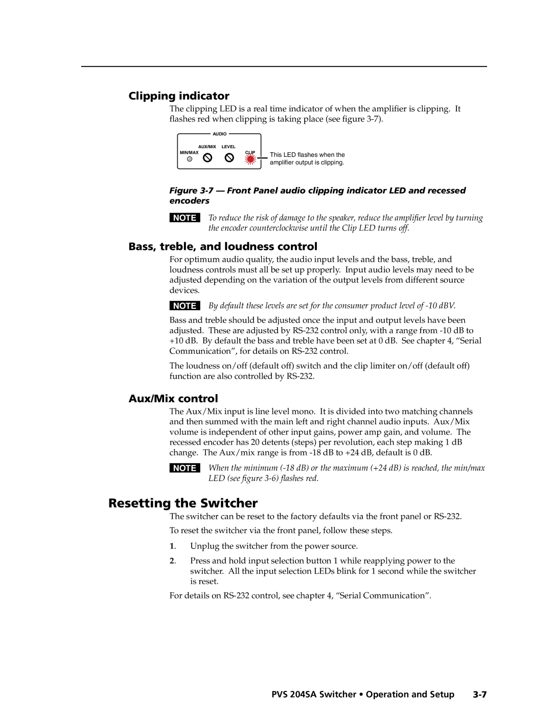
The clipping LED is a real time indicator of when the amplifier is clipping. It flashes red when clipping is taking place (see figure
AUDIO |
| |
AUX/MIX | LEVEL |
|
MIN/MAX | CLIP | This LED flashes when the |
|
| |
|
| amplifier output is clipping. |
Figure 3-7 — Front Panel audio clipping indicator LED and recessed encoders
NTo reduce the risk of damage to the speaker, reduce the amplifier level by turning the encoder counterclockwise until the Clip LED turns off.
Bass, treble, and loudness control
For optimum audio quality, the audio input levels and the bass, treble, and loudness controls must all be set up properly. Input audio levels may need to be adjusted depending on the variation of the output levels from different source devices.
NBy default these levels are set for the consumer product level of ‑10 dBV.
Bass and treble should be adjusted once the input and output levels have been adjusted. These are adjusted by
The loudness on/off (default off) switch and the clip limiter on/off (default off) function are also controlled by
Aux/Mix control
The Aux/Mix input is line level mono. It is divided into two matching channels and then summed with the main left and right channel audio inputs. Aux/Mix volume is independent of other input gains, power amp gain, and volume. The recessed encoder has 20 detents (steps) per revolution, each step making 1 dB change. The Aux/mix range is from
NWhen the minimum
Resetting the Switcher
The switcher can be reset to the factory defaults via the front panel or
To reset the switcher via the front panel, follow these steps.
1. Unplug the switcher from the power source.
2. Press and hold input selection button 1 while reapplying power to the
switcher. All the input selection LEDs blink for 1 second while the switcher is reset.
For details on
PRELIMINARY
PVS 204SA Switcher • Operation and Setup |
