Installation, cont’d
Control connection
H |
| |||||
| controlled via an RS‑232 connection directly from a host | Tx Rx IR 12V | ||||
| computer, a control system, or a MediaLink Controller (MLC). |
|
|
|
|
|
| For IR remote control, connect an Extron IR Link to this port. |
|
|
|
|
|
| A B C |
|
|
|
| |
|
|
|
|
|
| |
| Connect a cable between this port and an optional Extron MLC |
|
|
|
|
|
| MediaLink Controller or an optional IR Link IR signal repeater. |
|
|
|
|
|
•The MLC provides remote control of input switching and volume.
•The IR Link accepts modulated IR signals from a remote control
(e.g. the Extron IR 452 remote) enabling the remote control to be used for selecting the switcher inputs.
Wire the captive screw connector and connect it to a computer or control
system, an MLC, or an IR Link, as shown in figures
PRELIMINARY
|
| ||
Tx Rx IR | +12V | PVS 204SA |
|
|
|
| |
|
| Switcher's rear panel |
|
A B C D E | Projector | ||
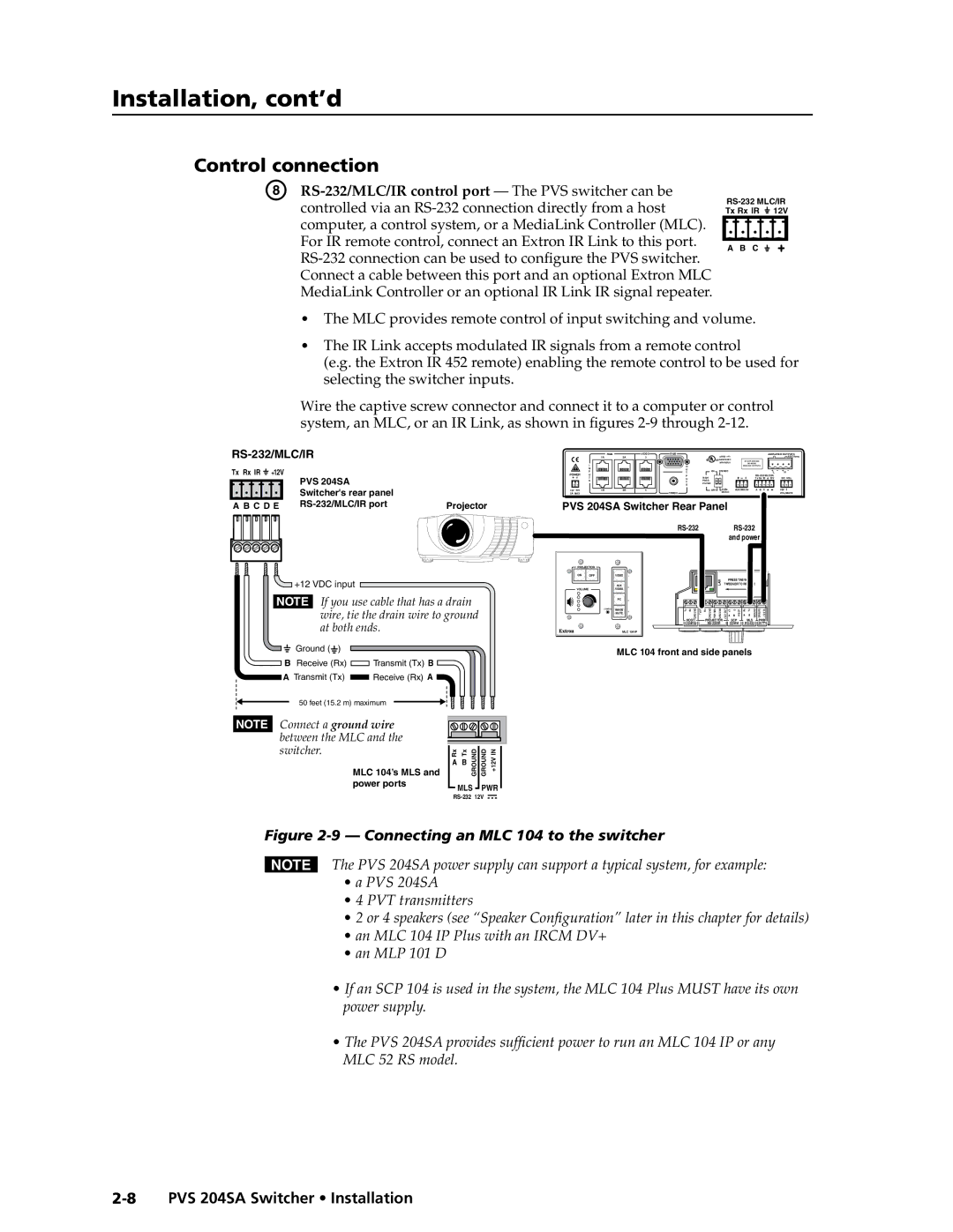
![]() +12 VDC input
+12 VDC input
NOTE If you use cable that has a drain wire, tie the drain wire to ground at both ends.
Ground ( ![]() )
)
B Receive (Rx) ![]() Transmit (Tx) B
Transmit (Tx) B
ATransmit (Tx) ![]() Receive (Rx) A
Receive (Rx) A ![]()
50 feet (15.2 m) maximum
NOTE Connect a ground wire |
|
|
between the MLC and the |
|
|
switcher. | Rx Tx | GROUND GROUND +12VIN |
MLC 104’s MLS and | A B |
power ports | MLS PWR | ||
| |||
|
|
|
|
|
| ||
|
| RGB | VIDEO | RGB |
|
|
|
|
| AMPLIFIED OUTPUTS | |
| 1A | 2A | 3 |
|
| LISTED 17TT |
|
|
|
| 4/8 Ohms |
|
|
|
|
|
| US AUDIO/VIDEO | DO NOT GROUND |
|
|
| |
| I |
|
|
|
| APPARATUS | OR SHORT |
|
|
| |
|
|
| O |
|
| SPEAKER OUTPUTS! |
|
|
| ||
| N |
|
| U | ON | STEREO |
|
|
| L | R |
POWER | P |
|
| T |
|
|
| ||||
U |
|
| P |
|
|
|
| ||||
| T |
|
| U | HIGH |
|
| Tx Rx IR | 12V | DC VOL | |
| S |
|
| T | PASS |
|
|
|
|
|
|
|
|
|
| FILTER |
|
|
|
|
|
| |
|
|
|
| S |
|
|
|
|
|
|
|
12V | 1B | 2B | 4 |
| OFF | DUAL | AUX/MIX IN | A B | C |
| 10V |
3A MAX |
|
|
| VIDEO |
| MONO |
|
|
|
| VOL/MUTE |
PVS 204SA Switcher Rear Panel
RS-232 RS-232 and power
PROJECTOR |
|
|
| |
ON | OFF | VIDEO | 1 |
|
|
|
| LAN | PRESS TAB WITH |
|
| AUX | TWEEKER TO REMOVE | |
|
| 2 |
| |
VOLUME |
| VIDEO |
|
|
| PC | 3 |
|
|
|
|
|
|
|
|
|
|
|
CONFIG | IMAGE | 4 | Tx | Rx GROUND | Tx/IR Rx GROUND PWRSNS GROUND | +12VOUT | +V | G | SCP | Rx | Tx | GROUND | GROUND +12VIN |
| MUTE |
| |||||||||||
|
|
|
|
|
|
| A | B | E | A | B |
|
|
|
|
|
| HOST/ | PROJECTOR |
|
| SCP |
|
| MLS |
| PWR |
|
|
| CONFIG |
| COMM |
| 12V | ||||||
| MLC 104 IP |
|
|
|
|
|
|
|
|
|
|
| |
MLC 104 front and side panels
Figure 2-9 — Connecting an MLC 104 to the switcher
NThe PVS 204SA power supply can support a typical system, for example:
•a PVS 204SA
•4 PVT transmitters
•2 or 4 speakers (see “Speaker Configuration” later in this chapter for details)
•an MLC 104 IP Plus with an IRCM DV+
•an MLP 101 D
•If an SCP 104 is used in the system, the MLC 104 Plus MUST have its own power supply.
•The PVS 204SA provides sufficient power to run an MLC 104 IP or any MLC 52 RS model.