Quick Start — PVS 204SA, cont’d
Step 5
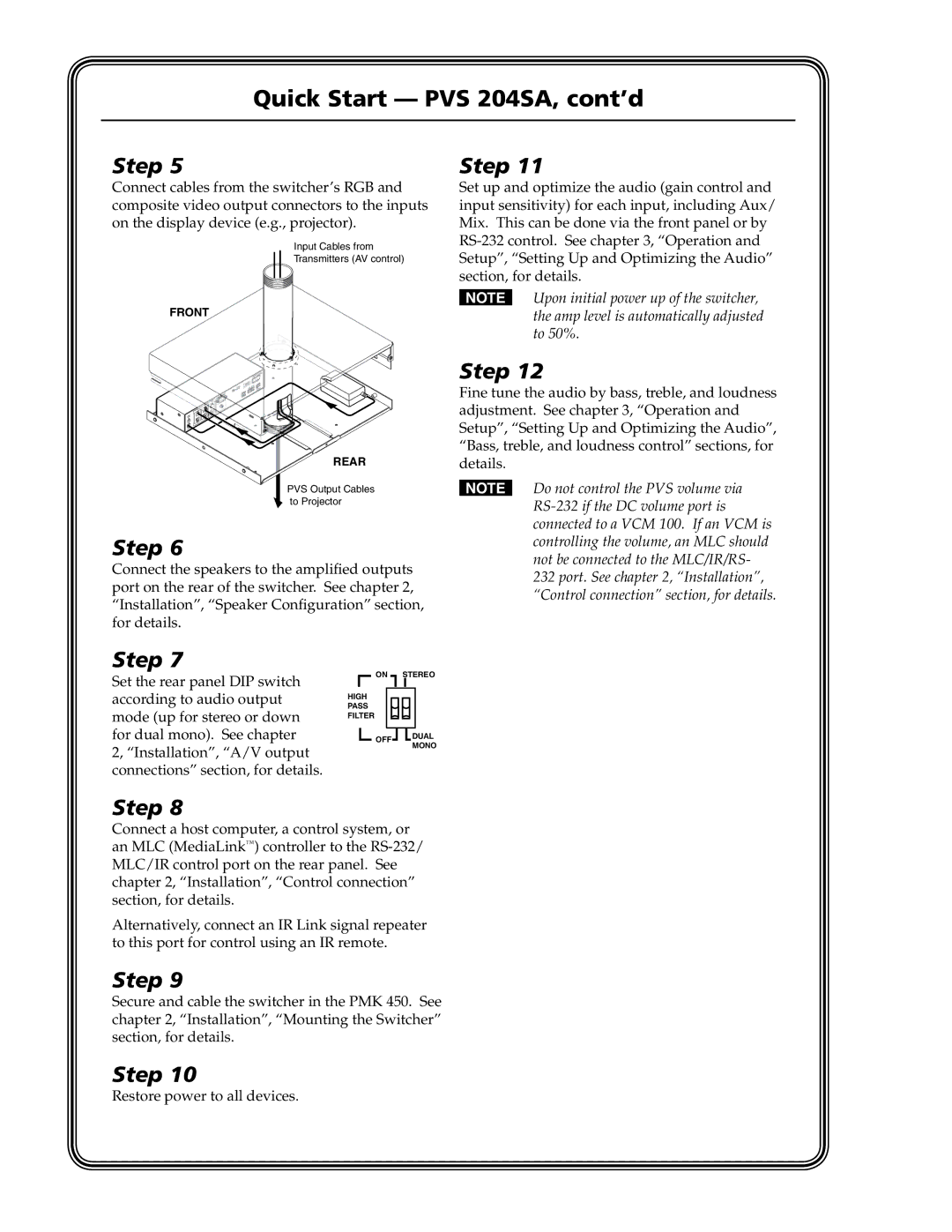
Connect cables from the switcher’s RGB and composite video output connectors to the inputs on the display device (e.g., projector).
Input Cables from
Transmitters (AV control)
FRONT
REAR
PVS Output Cables to Projector
Step 6
Connect the speakers to the amplified outputs port on the rear of the switcher. See chapter 2, “Installation”, “Speaker Configuration” section, for details.
Step 11
Set up and optimize the audio (gain control and input sensitivity) for each input, including Aux/ Mix. This can be done via the front panel or by
NUpon initial power up of the switcher, the amp level is automatically adjusted to 50%.
Step 12
Fine tune the audio by bass, treble, and loudness adjustment. See chapter 3, “Operation and Setup”, “Setting Up and Optimizing the Audio”, “Bass, treble, and loudness control” sections, for details.
NDo not control the PVS volume via
232 port. See chapter 2, “Installation”, “Control connection” section, for details.
Step 7
Set the rear panel DIP switch according to audio output mode (up for stereo or down for dual mono). See chapter 2, “Installation”, “A/V output connections” section, for details.
ON STEREO
HIGH
PASS
FILTER
![]() OFF
OFF![]()
![]() DUAL MONO
DUAL MONO
Step 8
Connect a host computer, a control system, or an MLC (MediaLink™) controller to the RS‑232/ MLC/IR control port on the rear panel. See chapter 2, “Installation”, “Control connection” section, for details.
Alternatively, connect an IR Link signal repeater to this port for control using an IR remote.
Step 9
Secure and cable the switcher in the PMK 450. See chapter 2, “Installation”, “Mounting the Switcher” section, for details.
Step 10
Restore power to all devices.
