2.Connect the cables to the receiver (continued).
b.Install any optional devices and connect their cables to the appropriate ports on the receiver base.
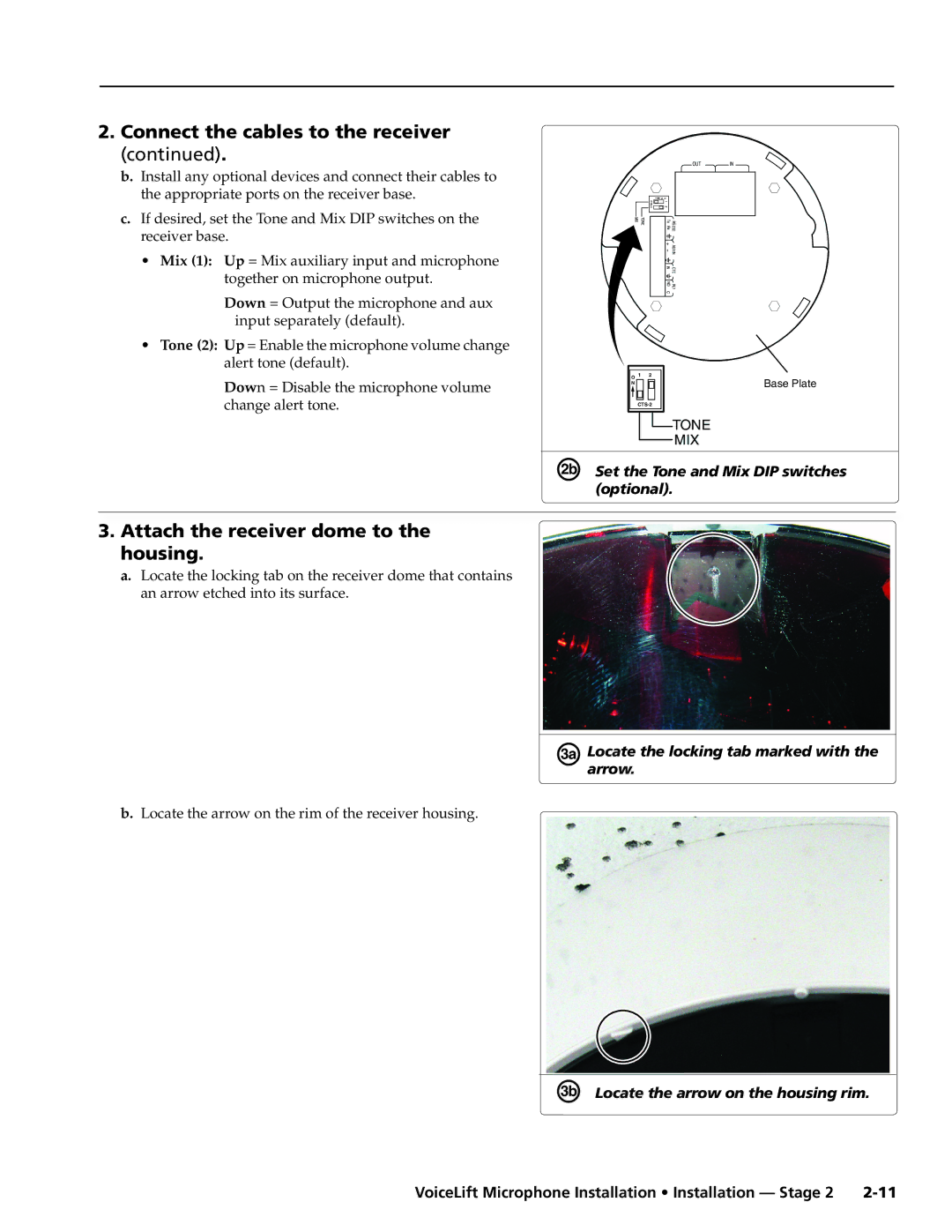
c.If desired, set the Tone and Mix DIP switches on the receiver base.
•Mix (1): Up = Mix auxiliary input and microphone
together on microphone output.
Down = Output the microphone and aux input separately (default).
•Tone (2): Up = Enable the microphone volume change alert tone (default).
Down = Disable the microphone volume change alert tone.
3.Attach the receiver dome to the housing.
a.Locate the locking tab on the receiver dome that contains an arrow etched into its surface.
b.Locate the arrow on the rim of the receiver housing.
OUT IN
| O N | |
CTS |
| 1 |
|
| |
| 2 | |
|
|
|
TONE MIX |
+ AUXIN
INCTC
NORLY
C
O 1 | 2 |
N | Base Plate |
TONE
MIX
ÉSet the Tone and Mix DIP switches (optional).
ÑLocatearrow. the locking tab marked with the
ÖLocate the arrow on the housing rim.
VoiceLift Microphone Installation • Installation — Stage 2 |