Optional Installation Example — Instant Alert
Installation Example — Setting Up an Instant Alert
The following pages describe an example of an optional instant alert setup, in which the relay port of the VLR 102 is connected to a digital I/O port of an Extron MLC 104 IP Plus. This enables
1.Connect the receiver to the MLC 104 IP Plus.
a.Wire one of the provided
b.Plug the communication cable into the receiver’s RLY port.
NIf the MLC controller and the PoleVault switcher are using separate power supplies, ground the
Relay port common pin to the receiver using a jumper between the common pin and the ground pin on either the Contact input, the Aux Input, or the
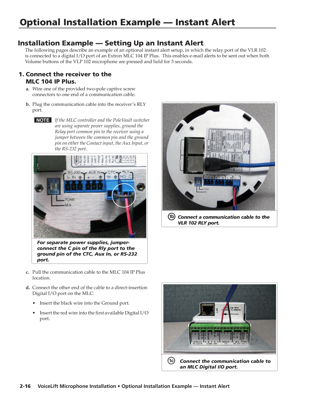
ÅConnect a communication cable to the
VLR 102 RLY port.
For separate power supplies, jumper- connect the C pin of the Rly port to the ground pin of the CTC, Aux In, or
c.Pull the communication cable to the MLC 104 IP Plus location.
d.Connect the other end of the cable to a
•Insert the black wire into the Ground port.
•Insert the red wire into the first available Digital I/O port.