45 specifications
The Fluke 45 is a versatile and high-precision Digital Multimeter that is designed for a wide range of applications in electrical testing, troubleshooting, and maintenance. Known for its reliability and advanced features, the Fluke 45 is an essential tool for engineers, technicians, and professionals who require accurate measurement capabilities.One of the standout features of the Fluke 45 is its ability to measure both AC and DC voltage and current. With a maximum input voltage of 1000 volts and current ranges up to 10 amps, users can conduct a variety of electrical tests with confidence. The device is equipped with an intuitive dual display, allowing for simultaneous viewing of multiple measurements. This feature enhances usability during complex diagnostics.
The Fluke 45 also boasts an impressive resolution of 0.1 mV and a basic accuracy of 0.25%, which translates to highly reliable readings. The auto-ranging capability simplifies the measurement process, automatically selecting the appropriate range based on the input signal, thus saving time and reducing user error.
In addition to voltage and current measurements, the Fluke 45 features resistance measurement capabilities, with a range of up to 40 MΩ. This makes it an effective tool for testing circuits, identifying faults, and ensuring the integrity of electrical systems. The continuity test function, complete with a built-in beeper, assists in quickly diagnosing wiring issues.
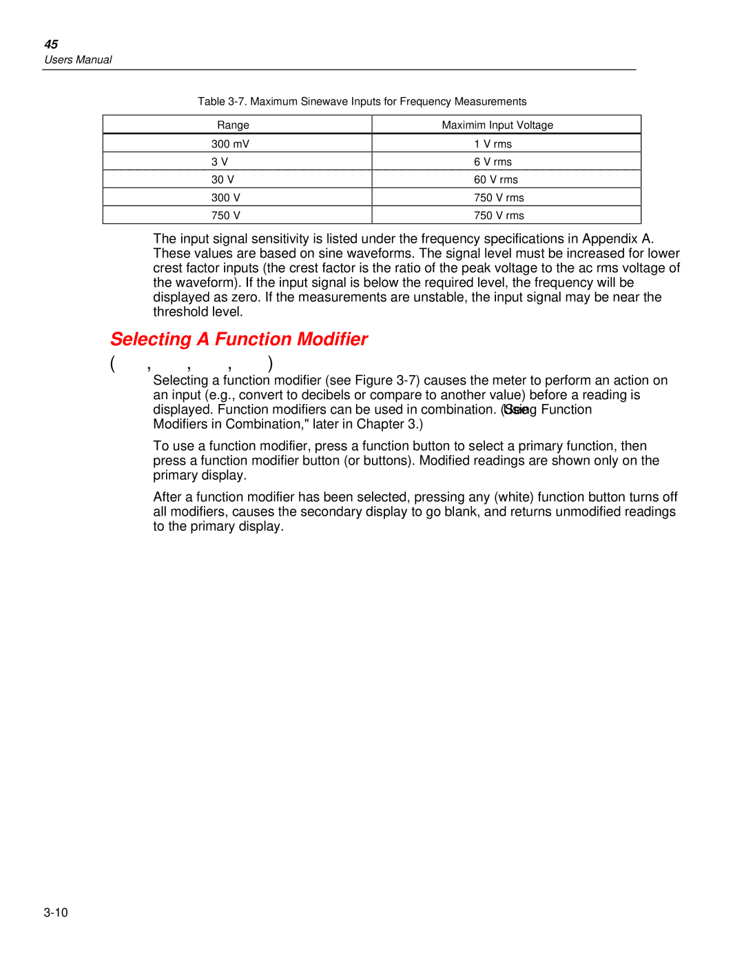
Another remarkable characteristic of the Fluke 45 is its frequency measurement capabilities, which can measure frequencies up to 1 MHz. This is particularly useful in applications involving signal analysis and troubleshooting oscillators.
Moreover, the Fluke 45 is designed with user convenience in mind. It is lightweight and portable, making it easy to carry around, whether on a job site or in a workshop. The rugged construction, reinforced with high-quality materials, ensures it can withstand harsh conditions often encountered in the field.
To enhance functionality, the Fluke 45 features a data hold function that freezes the displayed measurement for easier reporting. Additionally, it can store data for later retrieval, making it convenient for users who need to compile test results over time.
In summary, the Fluke 45 Digital Multimeter is an advanced instrument that combines precision, versatility, and user-friendly design. Its wide measurement capabilities, high accuracy, and durable build make it an invaluable tool for professionals in diverse electrical and electronic applications. Whether for routine maintenance or complex troubleshooting, the Fluke 45 stands out as a reliable partner in achieving accurate and efficient results.

