Operating the Meter Using the Computer Interface

5

How the Meter Processes Output

How the Meter Processes Output

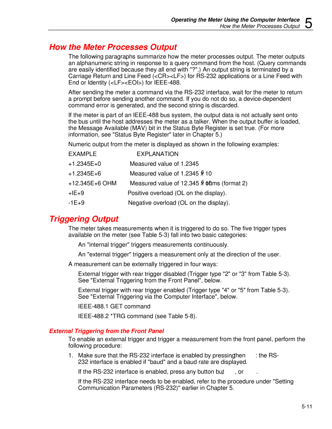
The following paragraphs summarize how the meter processes output. The meter outputs an alphanumeric string in response to a query command from the host. (Query commands are easily identified because they all end with "?".) An output string is terminated by a Carriage Return and Line Feed (<CR><LF>) for RS-232 applications or a Line Feed with End or Identity (<LF><EOI>) for IEEE-488.

After sending the meter a command via the RS-232 interface, wait for the meter to return a prompt before sending another command. If you do not do so, a device-dependent command error is generated, and the second string is discarded.

If the meter is part of an IEEE-488 bus system, the output data is not actually sent onto the bus until the host addresses the meter as a talker. When the output buffer is loaded, the Message Available (MAV) bit in the Status Byte Register is set true. (For more information, see "Status Byte Register" later in Chapter 5.)

Numeric output from the meter is displayed as shown in the following examples:

EXAMPLE

EXPLANATION

+1.2345E+0

Measured value of 1.2345

+1.2345E+6

Measured value of 1.2345 x 10⁶

+12.345E+6 OHM

Measured value of 12.345 x 10⁶ ohms (format 2)

+lE+9

Positive overload (OL on the display).

-1E+9

Negative overload (OL on the display).

Triggering Output

The meter takes measurements when it is triggered to do so. The five trigger types available on the meter (see Table 5-3) fall into two basic categories:

An "internal trigger" triggers measurements continuously.

An "external trigger" triggers a measurement only at the direction of the user. A measurement can be externally triggered in four ways:

External trigger with rear trigger disabled (Trigger type "2" or "3" from Table 5-3). See "External Triggering from the Front Panel", below.

External trigger with rear trigger enabled (Trigger type "4" or "5" from Table 5-3). See "External Triggering via the Computer Interface", below.

IEEE-488.1 GET command

IEEE-488.2 *TRG command (see Table 5-8).

External Triggering from the Front Panel

To enable an external trigger and trigger a measurement from the front panel, perform the following procedure:

1.Make sure that the RS-232 interface is enabled by pressing S, then R: the RS- 232 interface is enabled if "baud" and a baud rate are displayed.

If the RS-232 interface is enabled, press any button but E, U, or T.

If the RS-232 interface needs to be enabled, refer to the procedure under "Setting Communication Parameters (RS-232)" earlier in Chapter 5.

5-11

Page 67
Image 67
Fluke 45 user manual How the Meter Processes Output, Triggering Output, External Triggering from the Front Panel

45 specifications

The Fluke 45 is a versatile and high-precision Digital Multimeter that is designed for a wide range of applications in electrical testing, troubleshooting, and maintenance. Known for its reliability and advanced features, the Fluke 45 is an essential tool for engineers, technicians, and professionals who require accurate measurement capabilities.

One of the standout features of the Fluke 45 is its ability to measure both AC and DC voltage and current. With a maximum input voltage of 1000 volts and current ranges up to 10 amps, users can conduct a variety of electrical tests with confidence. The device is equipped with an intuitive dual display, allowing for simultaneous viewing of multiple measurements. This feature enhances usability during complex diagnostics.

The Fluke 45 also boasts an impressive resolution of 0.1 mV and a basic accuracy of 0.25%, which translates to highly reliable readings. The auto-ranging capability simplifies the measurement process, automatically selecting the appropriate range based on the input signal, thus saving time and reducing user error.

In addition to voltage and current measurements, the Fluke 45 features resistance measurement capabilities, with a range of up to 40 MΩ. This makes it an effective tool for testing circuits, identifying faults, and ensuring the integrity of electrical systems. The continuity test function, complete with a built-in beeper, assists in quickly diagnosing wiring issues.

Another remarkable characteristic of the Fluke 45 is its frequency measurement capabilities, which can measure frequencies up to 1 MHz. This is particularly useful in applications involving signal analysis and troubleshooting oscillators.

Moreover, the Fluke 45 is designed with user convenience in mind. It is lightweight and portable, making it easy to carry around, whether on a job site or in a workshop. The rugged construction, reinforced with high-quality materials, ensures it can withstand harsh conditions often encountered in the field.

To enhance functionality, the Fluke 45 features a data hold function that freezes the displayed measurement for easier reporting. Additionally, it can store data for later retrieval, making it convenient for users who need to compile test results over time.

In summary, the Fluke 45 Digital Multimeter is an advanced instrument that combines precision, versatility, and user-friendly design. Its wide measurement capabilities, high accuracy, and durable build make it an invaluable tool for professionals in diverse electrical and electronic applications. Whether for routine maintenance or complex troubleshooting, the Fluke 45 stands out as a reliable partner in achieving accurate and efficient results.