Digital Multitracker
8588 018 100
Safety Instructions
Table of Contents
100
101
MR-8 Main features About power supply
Introduction
About damages
Precautions upon handling the MR-8
About copyrights
Recording method
Song mode
Basics of the MR
About song
Bar/Beat/Clk
Time base
ABS time
Time counter
Trim control
Remain display
Input monitor and repro monitor
Names and Functions
Input a connectors
Input B connectors
Top panel left part
Phones VOL control
REVERB/DELAY Time control
Phones jacks 1
Effect keys
Top panel right part
UNDO/REDO /Y Z 9 entry key
Counter Reset / P Q R 6 entry key
Play Mode / a B C 1 entry key
Time Base Select / V W X 8 entry key
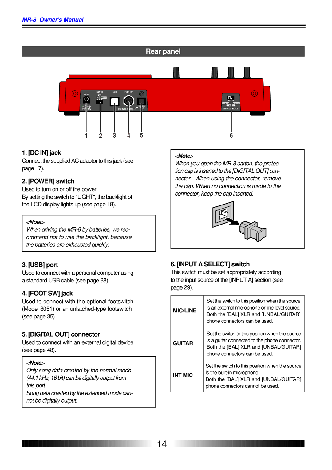
Rear panel
Bottom panel
Battery compartment
Side panel
Card slot Midi OUT jack
About recording medium
How to remove a CompactFlashTM card
How to insert a CompactFlashTM card
Inserting batteries
About the power
Connecting the AC adaptor
Turning on the unit
Turning on the LCD display backlight
Low battery display
Turning off the power
Listening the demo song
Tips Listening to the demo song again
While S01 Fostexfever is highlighted, press the Enter key
Press the Menu key to enter the menu mode
Preparation of a CompactFlashTM car d
Entry example
How to enter characters
Character entry keys
Preparation for recording onto a new card
Press the Menu key to quit the menu mode
Turn on the MR-8 power
Correction and deletion
Creating a song
Select the song mode using the Cursor or Cursor key
Creating a song/selecting a song
While Select Song is highlighted, press the Enter key
Selecting a desired song
Tip
While Card Format is highlighted, press the Enter key
Formatting a card
While System is highlighted, press the Enter key
Press the Enter key
Connections
Model AD-12A
Display
Home screen
Menu screen
Adjusting the display contrast
Selecting a time base
Recording onto stereo track
MR -8 recording basics
Recording onto a mono track
About simulation effect
Input level setting
Distortion setting
Insert effects
Recording onto a single track
Preparation for recording
Starting recording
Playing back the recorded track
Undo/redo
Preparation for recording
Set the Input a Select switch to MIC/LINE
Recording onto two tracks
Press the REC Select key for track 5/6
Starting recording
Playing back the recorded tracks
Punch in/out
Punch in/out using the keys on the top panel
Punch in/out using the footswitch
Auto punch in/out
Setting the punch-in and punch-out points
How to make auto punch in/out mode active
Rehearsal
Press the Play key to start playback of the song
Actual auto punch in/out
About part
Locate the recorder to the point before the punch- in point
Mic simulation effects
Using effects
Using the insert effects for recording
Amp simulation effects
Selecting an effect type
Selecting a delay type
Using the reverb or delay
Details of each effect type
Signal flow from a track to the effector
Adjusting the delay/reverb time
Adjusting the effect send levels
Details about each mastering effect type
Using the mastering effects
Selecting the desired effect type
Bouncing tracks
Example of track bouncing
7/8 mode
Signal flow of track bouncing
Selecting the bounce mode
5/6 mode
Rehearsal of track bounce
Panning control
Checking the bounced signals on track
Actual track bounce
Auto punch in/out of track bouncing
Exporting bounced data to a personal computer
Through 4 for recording
Mixdown
Analog mixdown
After finishing recording, stop both recorders Tip
Use the Master fader of the MR-8 to adjust the output level
Digital mixdown
Playback cueing
Playback functions
Basic playback
Playback between Locate a and B points
Auto return mode
Selecting a play mode
Auto play mode
Loop mode
Loop function in auto punch in/out mode
Locate ABS Zero function
Resetting the counter
Locate functions
Locate REC END function
Storing a Locate a point
Locating to counter zero
Storing a locate point
Locating to the Locate a or Locate B point
Storing a Locate B point
Locating
When System is highlighted, press the Enter key
Setting the pre-roll/post- roll
How to set the pre-roll/post-roll time
After selecting the pre-roll time, press the Enter key
Bar / 1 / 46 clk 1 bar / 1 / 00 clk
Setting the beat resolution
How to set the beat resolution
Bar / 4 / 51 clk 3 bar / 1 / 00 clk
Creating a new song
Press the Menu key to exit the menu mode
Editing a song
Selecting a desired song
Key, then press the Enter key
Editing a song name
After entering the name, move the cursor to
Deleting an unnecessary song
Use the Cursor / keys to select On, and press the Enter key
Protecting a song
Tips
Deleting the unnecessary file in a song
While Erase Track is highlighted, press the Enter key
Track editing
Undo/redo of track editing
Copying/pasting whole track data
Press the Enter key
Moving whole track data
Use the Cursor / keys to select source tracks to be moved
Exchange whole track data
Flashing
Part editing
Erasing a desired part
Copying to the clipboard
Use the Cursor / keys to select the tracks
While Paste Part is highlighted, press the Enter key
Pasting clipboard data
Use the Cursor / keys to select the desired tracks
Then press the Enter key
Moving the desired part to the other tracks
Use the Cursor / keys to select the move source tracks
Exchange parts between tracks
Use the Cursor / keys to select the exchange source tracks
Press the Enter key
Synchronization using MTC
Midi sync/MTC frame rate settings
Settings of the MR-8 and Midi sequencer
Synchronizing with Midi
Synchronization using Midi clock
Creating the signature/tempo map
Using the rhythm guide function
Setting the signature map
Use the Cursor / keys to enter
Use the Cursor key to flash 4/4 for Sig. setting
Changing the bar number or signature
Use the Cursor / keys to enter 3/4
To exit the menu mode, press the Menu key
Deleting an unnecessary bar/signature setting
Changing the bar offset
180
Creating the tempo map
First beat in bar 120
Third beat in bar First beat in bar 120
Use the Cursor key to flash 1 for Beat setting
Use the Cursor key to flash 120 for Tempo setting
Use the Cursor / keys to enter a desired tempo value
Deleting an unnecessary tempo setting
Editing the tempo map
Setting the click level
Enabling the file conversion
Procedure of file conversion
WAV file conversion
Editing a file name
Xporting data to a personal computer
Connection to a personal computer
Exporting a WAV file to a personal computer
Important note
Press the Menu key to exit the menu mode Tip
Initialized item Default setting
Initializing the MR
Trouble
Troubleshooting
Troubles for recording
Is the Record key flashing and does Light on the display?
Is shown on the screen?
Troubles for playback
Is the track fader for the playback track brought up?
Are the punch-in and punch-out points set correctly?
Other troubles
Troubles for power supply
Troubles for effect
Inputs/Outputs
MR- 8 specifications
Pin assignment of XLR connectors
Record/playback
When using the normal mode
Physical dimensions
Block diagram
When using the bounce mode 1-4 5/6 mode
When using the bounce mode 1-6 7/8 mode
Midi Implementation Chart
Model MR-8
Index
100
RP Stereo Headphone Optical Cable Powered near field studio
Optional accessaries
Stereo Headphone Foot switch Personal Monitor
Monitor
Declaration of EC Directive
376785