Freescale Semiconductor, Inc.
Connector Information
Logic Cables and Connectors
Table 3.1 | . Serial Connector and Cable Pin Assignments | ||
|
|
| |
Connector Pin | Mnemonic | Signal | |
|
|
|
|
1 |
| DCD | DATA CARRIER DETECT — Output signal that |
|
|
| indicates detection of an acceptable carrier |
|
|
| signal. |
|
|
|
|
2 |
| RX | RECEIVE DATA — Serial data output line. |
|
|
|
|
3 |
| TX | TRANSMIT DATA — Serial data input line. |
|
|
|
|
4 |
| DTR | DATA TERMINAL READY — Input signal that |
|
|
| indicates |
|
|
|
|
5 |
| GND | GROUND |
|
|
|
|
6 |
| DSR | DATA SET READY — Output signal that |
|
|
| indicates |
|
|
|
|
7 |
| RTS | REQUEST TO SEND — Input signal that |
|
|
| requests permission to transfer data. |
|
|
|
|
8 |
| CTS | CLEAR TO SEND — Output signal that indicates |
|
|
| a |
|
|
|
|
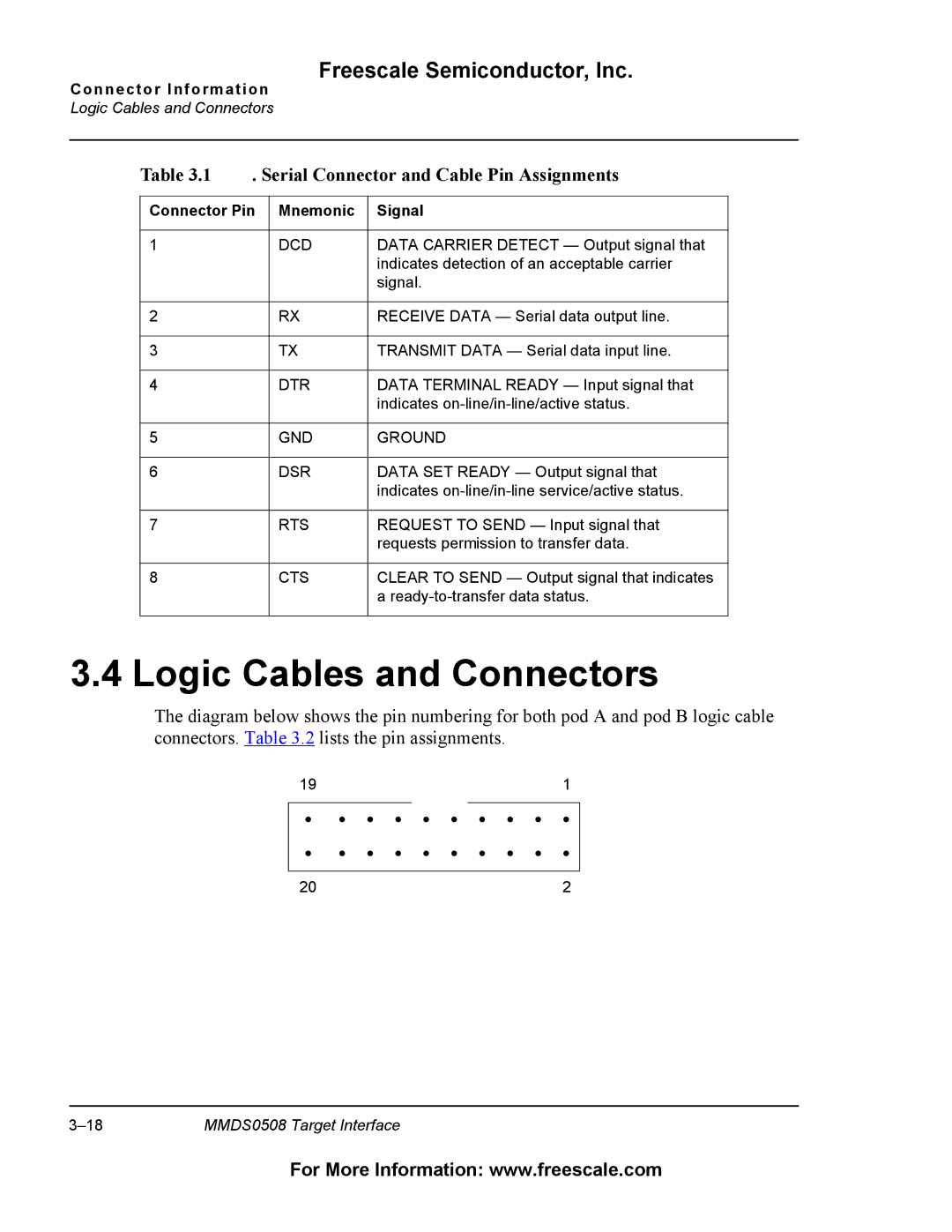
3.4 Logic Cables and Connectors
The diagram below shows the pin numbering for both pod A and pod B logic cable connectors. Table 3.2 lists the pin assignments.
19 |
|
|
|
|
|
|
|
| 1 |
|
|
|
|
|
|
|
|
|
|
• | • | • | • | • | • | • | • | • | • |
• | • | • | • | • | • | • | • | • | • |
|
|
|
|
|
|
|
|
|
|
20 |
|
|
|
|
|
|
|
| 2 |
MMDS0508 Target Interface |
For More Information: www.freescale.com