Freescale Semiconductor, Inc.
Installation
Configuring the Platform Board
Figure 2.3 Factory Test Header (J1)
(Ignore the alternate jumper position, which is reserved for factory tests.)
2.2.2 Port Voltage Control Headers (J2–J4)
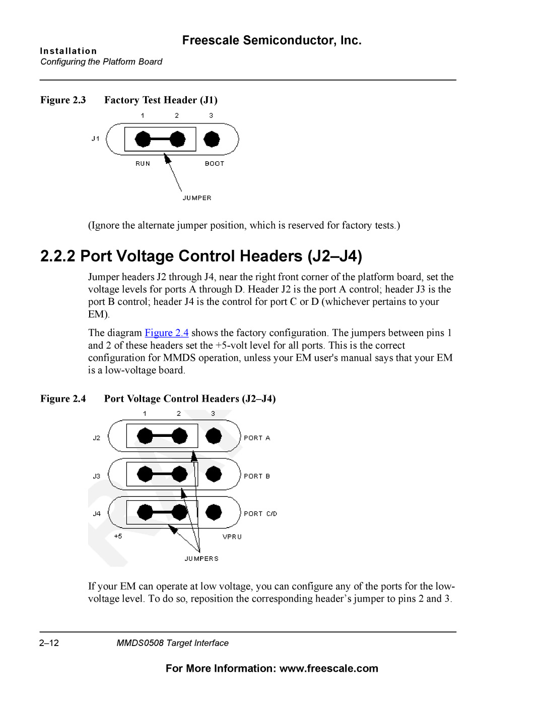
Jumper headers J2 through J4, near the right front corner of the platform board, set the voltage levels for ports A through D. Header J2 is the port A control; header J3 is the port B control; header J4 is the control for port C or D (whichever pertains to your EM).
The diagram Figure 2.4 shows the factory configuration. The jumpers between pins 1 and 2 of these headers set the
Figure 2.4 Port Voltage Control Headers (J2–J4)
If your EM can operate at low voltage, you can configure any of the ports for the low- voltage level. To do so, reposition the corresponding header’s jumper to pins 2 and 3.
MMDS0508 Target Interface |
For More Information: www.freescale.com