Freescale Semiconductor, Inc.
MMDS Target Component
4.10 Bus Analyzer
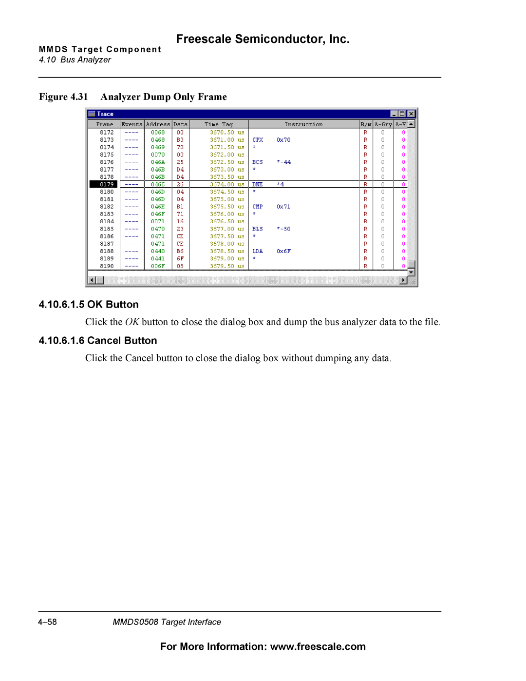
Figure 4.31 Analyzer Dump Only Frame
4.10.6.1.5 OK Button
Click the OK button to close the dialog box and dump the bus analyzer data to the file.
4.10.6.1.6 Cancel Button
Click the Cancel button to close the dialog box without dumping any data.
MMDS0508 Target Interface |
For More Information: www.freescale.com