Freescale Semiconductor, Inc.
|
|
|
|
| Connector Information | |
|
|
|
|
| Logic Cables and Connectors | |
|
|
|
|
|
|
|
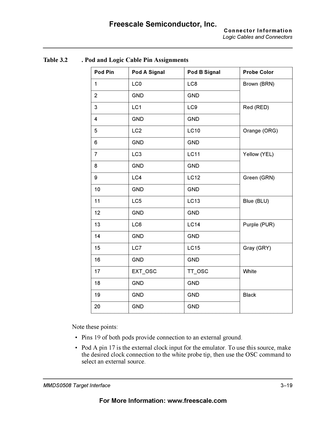
Table 3.2 | . Pod and Logic Cable Pin Assignments |
|
| |||
|
|
|
|
|
|
|
|
| Pod Pin | Pod A Signal | Pod B Signal |
| Probe Color |
|
|
|
|
|
|
|
|
| 1 | LC0 | LC8 |
| Brown (BRN) |
|
|
|
|
|
|
|
|
| 2 | GND | GND |
|
|
|
|
|
|
|
|
|
|
| 3 | LC1 | LC9 |
| Red (RED) |
|
|
|
|
|
|
|
|
| 4 | GND | GND |
|
|
|
|
|
|
|
|
|
|
| 5 | LC2 | LC10 |
| Orange (ORG) |
|
|
|
|
|
|
|
|
| 6 | GND | GND |
|
|
|
|
|
|
|
|
|
|
| 7 | LC3 | LC11 |
| Yellow (YEL) |
|
|
|
|
|
|
|
|
| 8 | GND | GND |
|
|
|
|
|
|
|
|
|
|
| 9 | LC4 | LC12 |
| Green (GRN) |
|
|
|
|
|
|
|
|
| 10 | GND | GND |
|
|
|
|
|
|
|
|
|
|
| 11 | LC5 | LC13 |
| Blue (BLU) |
|
|
|
|
|
|
|
|
| 12 | GND | GND |
|
|
|
|
|
|
|
|
|
|
| 13 | LC6 | LC14 |
| Purple (PUR) |
|
|
|
|
|
|
|
|
| 14 | GND | GND |
|
|
|
|
|
|
|
|
|
|
| 15 | LC7 | LC15 |
| Gray (GRY) |
|
|
|
|
|
|
|
|
| 16 | GND | GND |
|
|
|
|
|
|
|
|
|
|
| 17 | EXT_OSC | TT_OSC |
| White |
|
|
|
|
|
|
|
|
| 18 | GND | GND |
|
|
|
|
|
|
|
|
|
|
| 19 | GND | GND |
| Black |
|
|
|
|
|
|
|
|
| 20 | GND | GND |
|
|
|
|
|
|
|
|
|
Note these points:
•Pins 19 of both pods provide connection to an external ground.
•Pod A pin 17 is the external clock input for the emulator. To use this source, make the desired clock connection to the white probe tip, then use the OSC command to select an external source.
MMDS0508 Target Interface |
For More Information: www.freescale.com