Manuals
/
Fujitsu
/
Computer Equipment
/
Personal Computer
Fujitsu
500
user manual
Rear of the PC unit
Models:
500
1
15
80
80
Download
80 pages
19.87 Kb
12
13
14
15
16
17
18
19
Troubleshooting
Specification
Install
Connecting the power cable
Maintenance
Manual configuration
Problems
Hard disk access lamp
Command entry from keyboard
Parallel connector
Page 15
Image 15
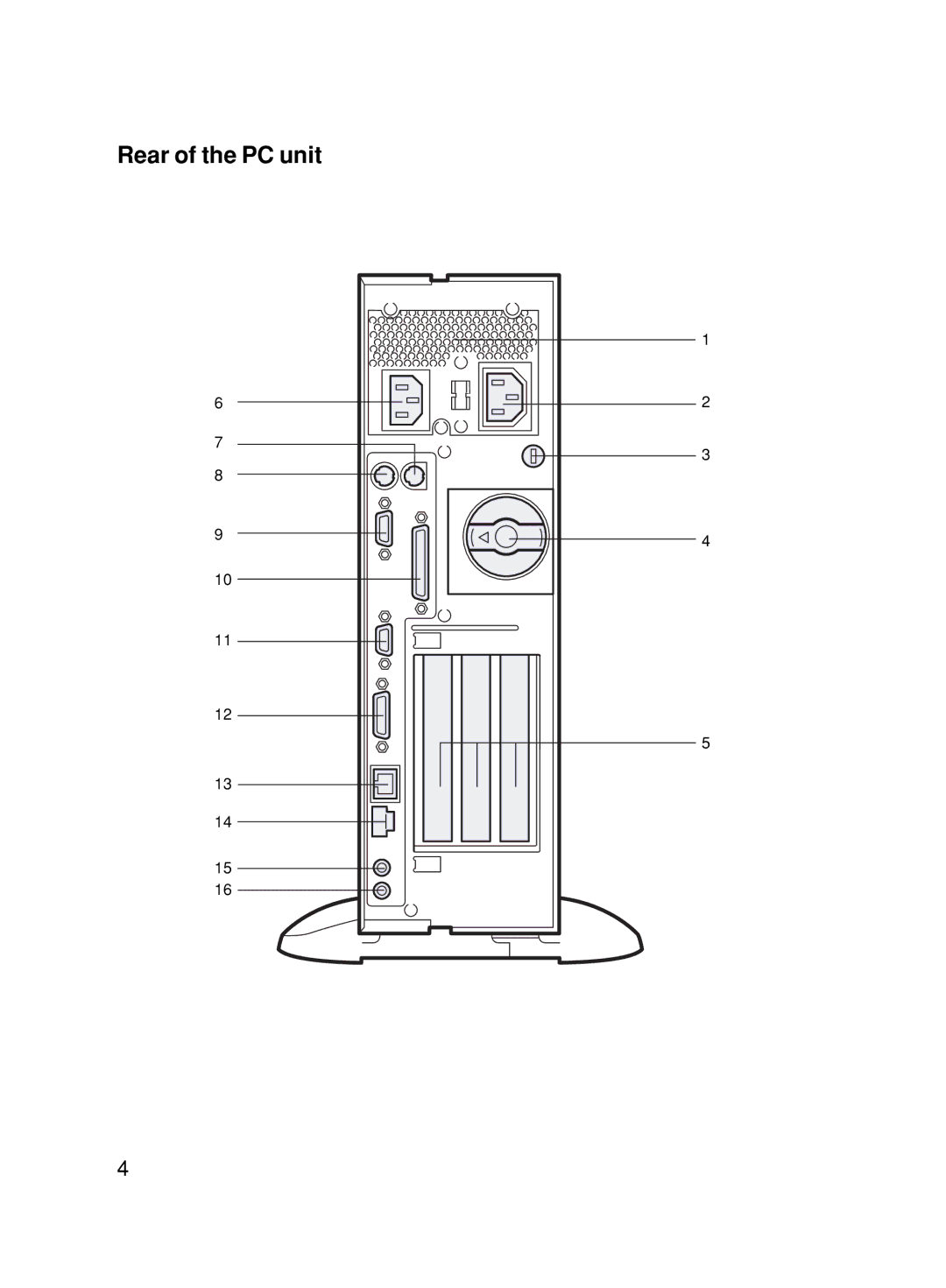
Rear of the PC unit
6
7
8
9
10
11
12
13
14
15
16
1
2
3
4
5
4
Page 14
Page 16
Page 15
Image 15
Page 14
Page 16
Contents
Deskpower 5000 Series User’s Manual
Important Safety Instructions
Iii
Safety product applications
Before Starting Your PC
For Safe Operations
Point
Conventions used in this manual
Illustrations
Command entry from keyboard
CD-ROM drive¥setup.exe Sample screens
Diskcopy a a
Rear surface of the equipment
Deskpower
Introduction
Manual configuration
Introduction
Content
Chapter
Hardware Specifications
Chapter
Front of the PC unit
Part Names and Functions
Floppy disk drive access lamp
Power lamp
Power switch
Hard disk access lamp
Rear of the PC unit
DVI connector
Keyboard connector Connect the keyboard Serial connector
Parallel connector
CRT connector
Power supply unit Inch front access bay
Inside the PC unit
Internal hard disk drive
Primary IDE connector IDE1
Internal battery
Dimm slots
Keyboard
Alt key
Caps Lock/Alphanumeric key
Ctrl control key
Windows key
Moving the mouse
Using the mouse
Using the mouse buttons
Mouse
Double-clicking
Pointing
Dragging
Using two feet
Installation
Installation area
Vertical placement
Using one foot
Mount the feet on the PC unit
Mount the disassembled foot on the PC unit
Horizontal placement
Disassemble the feet
Place the PC unit on the disassembled feet
Example of installation
Vertical placement
Horizontal placement
Connection
Connect the power cable to the outlet
Connect the power cable to the display
Connect the mouse
Connect the LAN cable to the network
Connect the keyboard
Connect the display cable to the PC unit
Connect the LAN cable
Connecting the power cable
Page
Turning On the Power
Turning on the power
Press the power switch on the display
Press the power switch on the PC
Turning Off the Power Supply
Turning off the power
Windows Me
Windows 98/95
Windows
Windows NT
Restarting the PC
Restarting
Point
CD-ROM
Press the Eject button
Inserting or removing a CD
Inserting a CD
Removing the CD
Floppy Disk
Inserting or removing a floppy disk Point
Inserting a floppy disk
Removing the floppy disk
Confirm that the Floppy disk access lamp is off
Hardware
Before Installing a Peripheral Device
Page
Removing the Cover
Removing the upper cover
Remove the upper cover
Removing the reinforcement bracket
Installing Memory Modules
Memory module installation procedure
Location of memory modules
Applicable memory modules
Memory module combinations
Installing Memory Modules
Insert a memory module into the slot
Installing an Expansion Card
Applicable expansion cards
Location of expansion cards
Remove the slot cover
Installing an Expansion Card
Windows NT models
Install the mounting bracket
Insert the expansion card into the slot
Plug the PC Turn on the PC Windows Me/98/95/2000 models
Location of internal options
Installing an Internal Option
Page
Installing a device in the 3.5-inch front access bay
Installing an Internal Hard Disk Drive
Make a setting on the option to be installed
Installing Other Internal Options
Install the internal option on the PC unit
Master Slave
Connect the flat cable
Connect the power cable
Troubleshooting
Problems
Windows Me/98/95
Characters entered using the keyboard are not displayed
Data cannot be read from the CD-ROM drive
Mouse cursor does not move
Technical Information
Cleaning CDs
Maintenance of the Hardware
Maintenance of the PC unit
Maintenance of the keyboard
Cleaning the floppy disk drive
Maintenance of the mouse
Additional Cautions
Preventing Television or Radio Interference
USB Windows Me/98/95/2000 models
Digital display output
USB keyboard Windows 98 models
Addition of a LAN card
Wakeup On LAN
Replacing the display
Power-saving function of display
Connecting the display
Video memory capacity display
Intel processor serial number
Power-saving function
International EnergyStar Program
Mouse with a scrolling function scrolling wheel
Hardware Specifications
PC unit specifications
Product name
CSMA/CD
LAN adapter specifications
Sound specifications
Graphical specifications
Connector specifications
TXC+
LAN connector 100BASE-TX/10BASE-T
Mouse connector
Keyboard connector
CD-ROM drive
Index
Mouse Clicking
Top
Page
Image
Contents