5.4Mounting HDDs
5.4.1Check before mounting
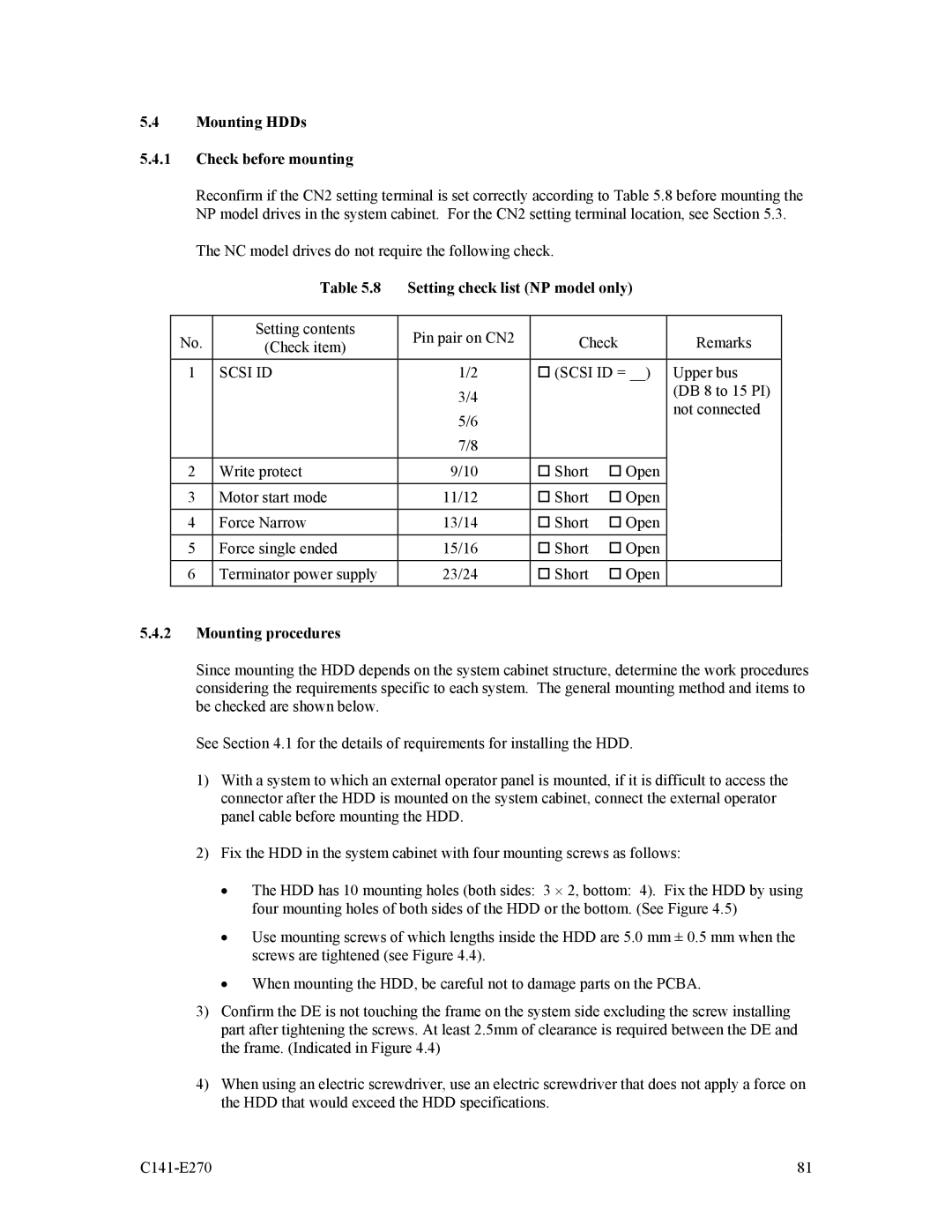
Reconfirm if the CN2 setting terminal is set correctly according to Table 5.8 before mounting the NP model drives in the system cabinet. For the CN2 setting terminal location, see Section 5.3.
The NC model drives do not require the following check.
| Table 5.8 | Setting check list (NP model only) |
| ||
|
|
|
|
|
|
No. | Setting contents | Pin pair on CN2 | Check | Remarks | |
(Check item) | |||||
1 | SCSI ID | 1/2 | (SCSI ID = __) | Upper bus | |
|
| 3/4 |
|
| (DB 8 to 15 PI) |
|
|
|
| not connected | |
|
| 5/6 |
|
| |
|
|
|
|
| |
|
| 7/8 |
|
|
|
|
|
|
|
|
|
2 | Write protect | 9/10 | Short | Open |
|
|
|
|
|
|
|
3 | Motor start mode | 11/12 | Short | Open |
|
|
|
|
|
|
|
4 | Force Narrow | 13/14 | Short | Open |
|
|
|
|
|
|
|
5 | Force single ended | 15/16 | Short | Open |
|
|
|
|
|
|
|
6 | Terminator power supply | 23/24 | Short | Open |
|
|
|
|
|
|
|
5.4.2Mounting procedures
Since mounting the HDD depends on the system cabinet structure, determine the work procedures considering the requirements specific to each system. The general mounting method and items to be checked are shown below.
See Section 4.1 for the details of requirements for installing the HDD.
1)With a system to which an external operator panel is mounted, if it is difficult to access the connector after the HDD is mounted on the system cabinet, connect the external operator panel cable before mounting the HDD.
2)Fix the HDD in the system cabinet with four mounting screws as follows:
•The HDD has 10 mounting holes (both sides: 3 ⋅ 2, bottom: 4). Fix the HDD by using four mounting holes of both sides of the HDD or the bottom. (See Figure 4.5)
•Use mounting screws of which lengths inside the HDD are 5.0 mm ± 0.5 mm when the screws are tightened (see Figure 4.4).
•When mounting the HDD, be careful not to damage parts on the PCBA.
3)Confirm the DE is not touching the frame on the system side excluding the screw installing part after tightening the screws. At least 2.5mm of clearance is required between the DE and the frame. (Indicated in Figure 4.4)
4)When using an electric screwdriver, use an electric screwdriver that does not apply a force on the HDD that would exceed the HDD specifications.
| 81 |