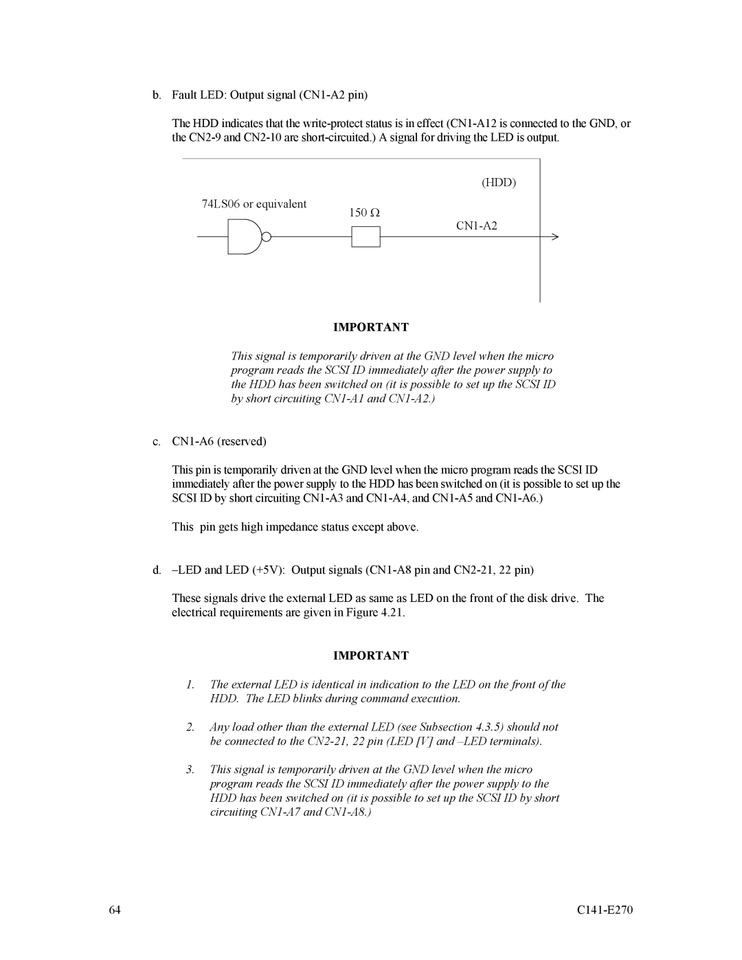
b.Fault LED: Output signal
The HDD indicates that the
74LS06 or equivalent
(HDD)
150 Ω
IMPORTANT
This signal is temporarily driven at the GND level when the micro program reads the SCSI ID immediately after the power supply to the HDD has been switched on (it is possible to set up the SCSI ID by short circuiting
c.
This pin is temporarily driven at the GND level when the micro program reads the SCSI ID immediately after the power supply to the HDD has been switched on (it is possible to set up the SCSI ID by short circuiting
This pin gets high impedance status except above.
d.
These signals drive the external LED as same as LED on the front of the disk drive. The electrical requirements are given in Figure 4.21.
IMPORTANT
1.The external LED is identical in indication to the LED on the front of the HDD. The LED blinks during command execution.
2.Any load other than the external LED (see Subsection 4.3.5) should not be connected to the
3.This signal is temporarily driven at the GND level when the micro program reads the SCSI ID immediately after the power supply to the HDD has been switched on (it is possible to set up the SCSI ID by short circuiting
64 |
|