XG2600 Hardware Guide | Chapter 2 Installation |
|
|
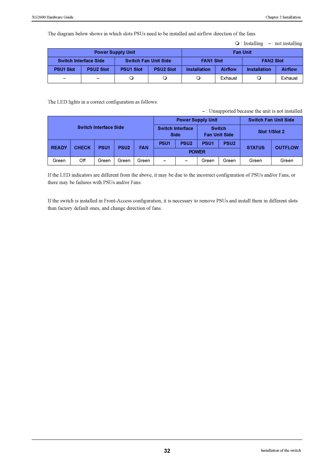
The diagram below shows in which slots PSUs need to be installed and airflow direction of the fans.
: Installing
| Power Supply Unit |
|
| Fan Unit |
| ||
Switch Interface Side | Switch Fan Unit Side | FAN1 Slot | FAN2 Slot | ||||
PSU1 Slot | PSU2 Slot | PSU1 Slot | PSU2 Slot | Installation | Airflow | Installation | Airflow |
– | – | | | | Exhaust | | Exhaust |
|
|
|
|
|
|
|
|
The LED lights in a correct configuration as follows:
|
|
|
|
|
|
| Power Supply Unit |
| Switch Fan Unit Side | ||
| Switch Interface Side |
| Switch Interface | Switch | Slot 1/Slot 2 | ||||||
|
|
|
|
|
| Side | Fan Unit Side | ||||
|
|
|
|
|
|
|
| ||||
READY | CHECK | PSU1 | PSU2 | FAN | PSU1 |
| PSU2 | PSU1 | PSU2 | STATUS | OUTFLOW |
|
| POWER |
| ||||||||
|
|
|
|
|
|
|
|
|
| ||
Green | Off | Green | Green | Green | – |
| – | Green | Green | Green | Green |
|
|
|
|
|
|
|
|
|
|
|
|
If the LED indicators are different from the above, it may be due to the incorrect configuration of PSUs and/or Fans, or there may be failures with PSUs and/or Fans.
If the switch is installed in
32 | Installation of the switch |