Manuals
/
Gateway
/
Computer Equipment
/
Personal Computer
Gateway
EC14
manual
Models:
EC14
1
127
174
174
Download
174 pages
35.6 Kb
124
125
126
127
128
129
130
131
Troubleshooting
Specs
System Block Diagram
Bluetooth
Password
Euro symbol
Indicators
Dimension
Common Problems
Bios Setup Utility
Page 127
Image 127
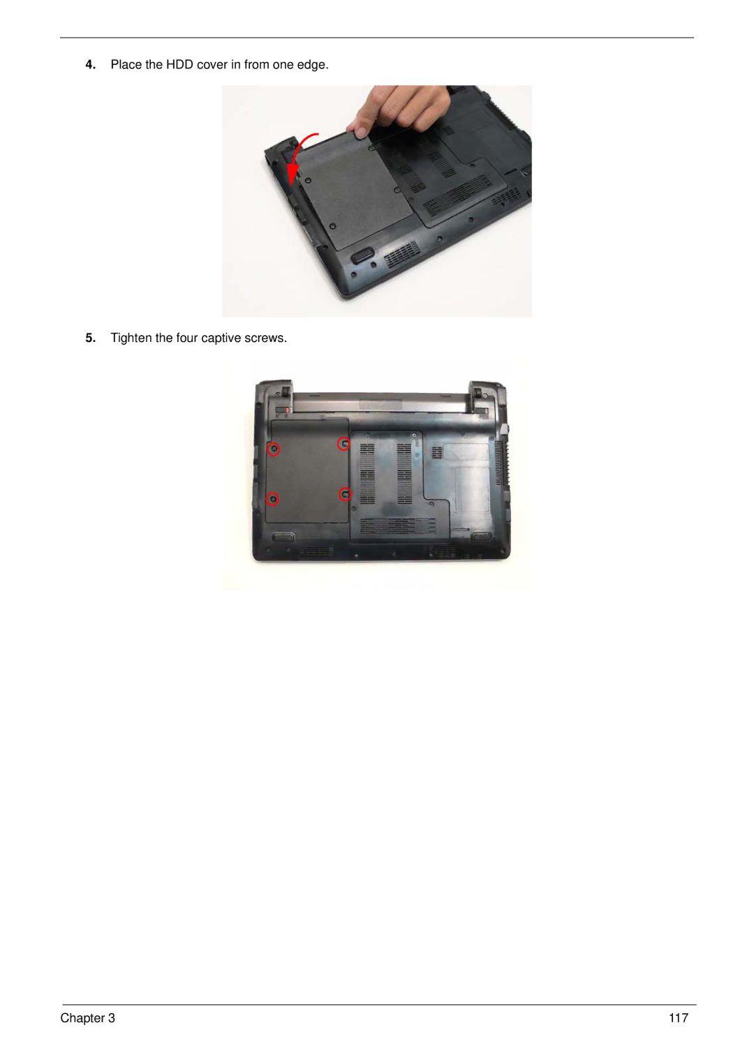
4.
Place the HDD cover in from one edge.
5.
Tighten the four captive screws.
Chapter 3
117
Page 126
Page 128
Page 127
Image 127
Page 126
Page 128
Contents
Gateway EC18/EC14 Service Guide
Revision History
III
Copyright
Conventions
Preface
Page
Table of Contents
Viii
Troubleshooting 121
FRU Field Replaceable Unit List 141
Table of Contents
Chapter
Features
Input devices
Dimensions and Weight
Power subsystem
Privacy control
Non-operating 20% to 80% Chapter
B ST a C K UP 8L H DI
System Block Diagram
Top View
Indicates when the HDD is active
Your Notebook Tour
LCD View
Closed Front View
Hdmi
Left View
Right View
USB
Rear View
Base View
Icon Function Description
Indicators
HDD
Function Left Button Right Button Main TouchPad
TouchPad Basics
Lock Keys and embedded numeric keypad
Using the Keyboard
Key Description
Windows Keys
Hotkey Icon Function Description
Hot Keys
Special Keys
Euro symbol
US dollar sign
Cache Package Power Acer P/N Speed Tech Size
Hardware Specifications and Configurations
Processor Specification
Processor Specifications
Video Specifications
North Bridge Specifications
South Bridge Specifications
System Memory Specification
RPM
Hard Disk Drive Interface Specifications
Internal transfer
LCD Specifications
Bios
Atheros AR8131L
Bluetooth Specification
Audio Codec and Amplifier Specification
LAN Interface Specification
Media Card Reader Specification
Keyboard Specification
Camera Specifications
802.11b
Wireless LAN Specification
Battery Specification Cell
802.11g
Specification
Chapter
Navigating the Bios Utility
Bios Setup Utility
Parameter Description
Information
Parameter Description Format/Option
Main
Parameter Description Option
Setting a Password
Enabled or
Security
Removing a Password
Enter New Password
Continue
Changing a Password
USB Cdrom
Boot
Exit Exit Saving Changes
Exit
Bios Flash Utility
HTS545032B9A300
DOS Flash Utility
WinFlash Utility
Remove HDD Password
Remove HDD/BIOS Password Utilities
Select Enter Unlock Password and press Enter
Removing Bios Passwords
Using DMITools
Using Boot Sequence Selector
Miscellaneous Utilities
Example 1 Read DMI Information from Memory
Using the LAN MAC Utility
Chapter
Replacement Requirements
Disassembly Requirements
Related Information
Pre-disassembly Instructions
M2*3.0 I BNI,NYLOKIRON
Disassembly Process
Main Screw List Quantity Acer Part Number
M2.0X2.5-IBNINYLOK Iron
External Modules Disassembly Flowchart
External Module Disassembly Process
Screw List Step Quantity
Removing the Battery Pack
Removing the Dummy Card
Removing the Hard Disk Drive Module
Chapter
Removing the Dimm Module
Pull the memory module out
Removing the Wlan Module
Screw List Step Quantity Screw Type
Main Unit Disassembly Flowchart
Main Unit Disassembly Process
Screw List Step Quantity
Removing the Keyboard
Chapter
Removing the Upper Cover
Disassembly
Screw List Step Size Quantity Screw Type Upper Cover M2*3
Screw List Step Size Quantity Screw Type
Removing the Button Board
Screw List Step Size Quantity Screw Type Button board M2*3
Page
Removing the LCD Module
LCD Module M2*5 Disassembly Lift the LCD module away Chapter
Removing the LED Board
Page
Removing the Bluetooth Module
Removing the I/O Board
Board Disassembly
Removing the Mainboard
Chapter
Removing the CRT Board
Removing the Thermal Module
Removing the RTC Battery
Removing the Speaker Modules
LCD Module Disassembly Flowchart
LCD Module Disassembly Process
Removing the LCD Bezel
Removing the Camera Board
Removing the LCD Panel
Page
Removing the LCD Brackets
Removing the FPC Cable
Removing the Antennas
Remove the antennas completely Chapter
Replacing the Antennas
LCD Reassembly Procedure
Page
Replacing the FPC Cable
Replacing the LCD Brackets
Replacing the LCD Panel
Screw List Step Quantity Screw Type LCD Panel Assembly 2x3
Apply adhesive and stick the microphone down Chapter
Replacing the Camera Board
Replacing the LCD Bezel
Chapter
Replacing the Speaker Modules
Main Unit Reassembly Process
Replacing the RTC Battery
Replacing the Thermal Module
Replacing the CRT Board
Replacing the Main Board
Screw List Step Quantity Screw Type Main Board Assembly 2x3
Connect the speaker connector
Replacing the I/O Card
Screw List Step Quantity Screw Type Card Assembly 2x3
100 Chapter
Replacing the Bluetooth Module
Replacing the LED Board
Screw List Step Quantity Screw Type LED Board Assembly M2*3
M2x5
Replacing the LCD Module
Page
Relay the Wlan cables around and through the lower case
Replacing the Button Board
108 Chapter
Page
Replacing the Upper Cover
Screw List Step Size Quantity Screw Type
Replacing the Keyboard
Screw List Step Size Quantity Screw Type Wlan Assembly M2*3
Replacing the Wireless LAN Module
114 Chapter
Replacing the Dimm Module
Replacing the Hard Disk Drive
Page
Replacing the Battery
Replace the Dummy Card
120 Chapter
Symptoms Verified Go To
Common Problems
Computer Shuts down Intermittently
Power On Issue
No Post or Video
No Display Issue
Abnormal Video Display
Random Loss of Bios Settings
LCD Failure
Built-In Keyboard Failure
TouchPad Failure
Internal Speaker Failure
Sound Problems
Select Set up microphone
Microphone Problems
Internal Microphone Failure
Select Repair your computer
HDD Not Operating Correctly
Select Startup Repair
Other Failures
USB Failure Right up/down side
Undetermined Problems
Intermittent Problems
Dimm
Post Routine Description Code
Post Code Reference Tables
SNP
Post Routine Description Code
136 Chapter
Mainboard Top View
Mainboard Bottom View
Mainboard Cmos Discharge
Clearing Password Check and Bios Recovery
Steps for Bios Recovery from USB Storage
Bios Recovery by Crisis Disk
Bios Recovery Boot Block
Bios Recovery Hotkey
FRU Field Replaceable Unit List
Gateway EC18/EC14 Exploded Diagrams
Description Part Number
Main Assembly
Chapter 143
LCD Assembly
FRU List
Power Cord US-110V Bsmi
Cable Power Cord US 3PIN Rohs
Power Cord AU W/LABEL 3 PIN
Power Cord UK 3PIN
HDD Cover Black
Upper Case Assy RED W/TP, FFC Cable *2
Lower Case Assy W/SPEAKER for 3G
Lower Case Assy W/SPEAKER for NON 3G
Sata LF F/WFG011J
Sata HDD/HARD Disk Drive
Sata LF F/W FG011J
Sata LF F/WFG001J
For NON 3G Mainboard GS45 ICH9M CPU CM723B W/O RAM
LCD
Mainboard Mainboard GS45 ICH9M CPU SU3500B W/O RAM
For 3G Mainboard GS45 ICH9M CPU SU3500B W/O RAM
Screw List
Model Acer Part No Description
Appendix a
AAP
NLED11.6WXGAG UMA SO2GBII6
Model
Memory
Chip
NIS
Tooth
BGN
1-Build SP1x2HMW 6CELL2.8 EC1802h
Appendix B
Type Description Camera
SB Chipset
Keyboard
Mouse
NB Chipset
WNC Pifa
Type Description WiFi Antenna
BGN Intel
Appendix C
Online Support Information
160
Bios
Flowchart
Block Diagram
Bios
Top
Page
Image
Contents