XM Plural-Component Sprayers313289S
Contents
Manual Description
Related Manuals
Component Manuals in U.S. English
Fire and Explosion Hazard
Intrinsic Safety
Equipment Misuse Hazard
Location Category Key
Models
XM a XM B XM D XM C XM E
Approvals
Isocyanate Hazard
Overview
Material Self-Ignition
Moisture Sensitivity Isocyanates
Keep Components a and B Separate
Components a and B
Changing Materials
Lift Using a Hoist
Lift Using a Forklift
Before Repair
Location Proper Lifting of Sprayer
Relieve Pump Fluid Pressure
Pressure Relief Procedure
Relieve a and B Fluid Pressure
Flush Before Using Equipment
Flush Mixed Material
Flush
Flush Mix Manifold
Use Solvent Pump
Follow Pressure Relief Procedure,
Empty and Flush Entire System new sprayer or end of job
Procedure
Guidelines
Turn on heaters until fluid lines are clear of sol- vent
R3123593132896 R3123593132897
Relieve pressure. See Pressure Relief Procedure,
Cleaning Procedure
Shutdown Entire System
Flush Entire System new sprayer or end of job on
XM Setup and Troubleshooting Guide
Problem Cause Solution
Troubleshooting
See Appendix a in manual
Tor Power Supply Control Compo
View Alarms
Alarms
Diagnose Alarms
Clear Alarms
Alarm Code Alarm Problem When Active Cause Solution
Alarm Codes and Troubleshooting
See Pump Assembly,
Pump Test Daily Check Recommended
Optional User-Settable Maintenance Warnings
Optional User-Settable Spray Limits
Mode Control Logic Alarms
Possible Alarms by Mode
R2D
Stop
Alarm Code Key
LED Diagnostic Information
Module Status LED Signal Diagnosis Solution
What Alert Where
Replace Air Filter Element
Repair
Main Air Inlet Manifold Filter
Both Filters
Remove Shroud
User Interface/Control Box
Replace Solenoid Module
DVA DVB
Replace USB Module
Update USB Module Software
Load software. See Update USB Module Soft Ware
Replace Fluid Control Module FCM
Update Fluid Control Module FCM Software
Load software. See Update Fluid Control Module FCM Software
Display
Replace Alarm
Upgrade Software
Replace Display
Replace Display Battery
Replace Front Panel
Wall Power Supply Control Components
Replace Power Supply Module
Alternator Module Repair
Alternator Power Supply Control Components
FCM
USB
Replace Alternator Regulator
Air Controls
Gauge 326 319 330 340 331
Mix Manifold Assembly
Fluid Control Assembly
Dosing Valve Assembly
Replace Fluid Pressure Sensor
Temperature RTD Sensor
Sensors
Remove Displacement Pump
Pump Assembly
Remove Pump Assembly
Remove Air Motor
Solvent Pump
Service and Repair
Fluid Heaters
Replace
Simplified Electrical Schematic, XM Sprayer with Alternator
Electrical Schematics
Electrical Schematics 313289S
Simplified Pneumatic Schematic, XM Sprayer with Alternator
313289S
Detailed Electrical Schematic, XM Sprayer with Alternator
Blue Green
Detailed Electrical Schematic, XM Sprayer with Alternator
XM Plural Component Sprayer with Wall Power
Simplified Electrical Schematic, XM Sprayer with Wall Power
Simplified Pneumatic Schematic, XM Sprayer with Wall Power
Manual
With Wall Power
Detailed Electrical Schematic, XM Sprayer with Wall Power
Box
Wiring Schematics
Fluid
Heaters
Hopper Heaters
Junction Box Wiring Schematics 313289S
XM Plural-Component Sprayers
Parts
XM1, XM2
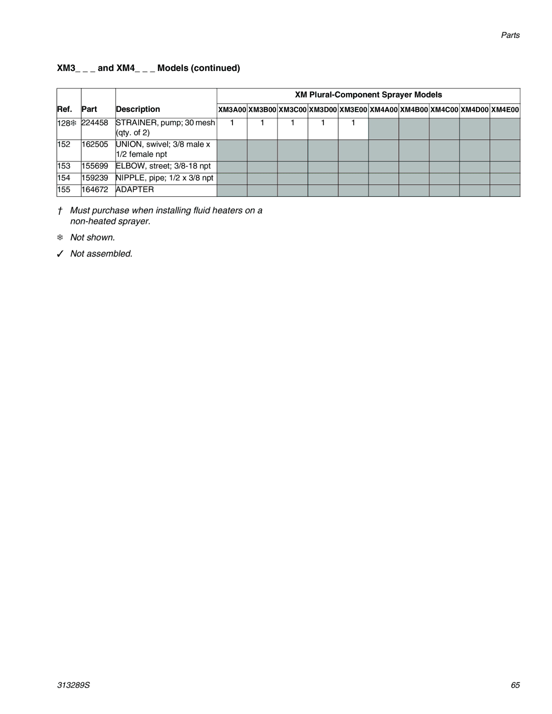
XM3, XM4
XM7, XM8 Models
XMB and XME
XM5, XM6
113 114 120 121 122 135 137 115
Common Parts
Fluid Control Assembly Parts
Part Description Qty
See Air Controls Module Parts,
XM1 and XM2 Models
Parts Varying by Model
XM1 and XM2 Models
XM Plural-Component Sprayer Models Part Description
XM3 and XM4 Models
XM3 and XM4 Models
XM5 and XM6 Models
Adapter
XM7 and XM8 Models
XM7 and XM8 Models
Control Box 255771 Parts
Air Power and Electric Power Versions
Part Description
Label
MODULE, USB
Base
Alternator Assembly
Control Box Power Supply Options
Wall Power Supply Assembly Cable Connections
Wall Power Supply Assembly
Adapter
Air Controls Module 255761 Parts
Regulator
Coupling
Junction Box 256540 Parts
Switch 25A
Circuit Breaker 25A
Circuit Breaker 10A
SENSOR, RTD
Fluid Control Assembly Parts
CAP Plug
Air Inlet Manifold 255762 Parts
Swivel
Turbine
Alternator Module 255728 Parts
Repair and Spare Parts Reference
Part Description Qty Part of Assembly
Accessories and Kits
Desiccant Dryer Kit
Electric Heated Hose Power Supply Kit
Shutoff/Check Valve Kit
Caster Kit
System Dimensions without Hoppers
Dimensions
Two 20-Gallon Hoppers Rear Mounted
System Dimensions with Hoppers
Two 20-Gallon Hoppers Side Mounted
Two 7-Gallon Hoppers
One 20-Gallon Hopper and One 7-Gallon Hopper
PTFE, Uhmwpe
Technical Data
Graco Information
Graco Standard Warranty