4.Position the
5000
3000
4000
6000
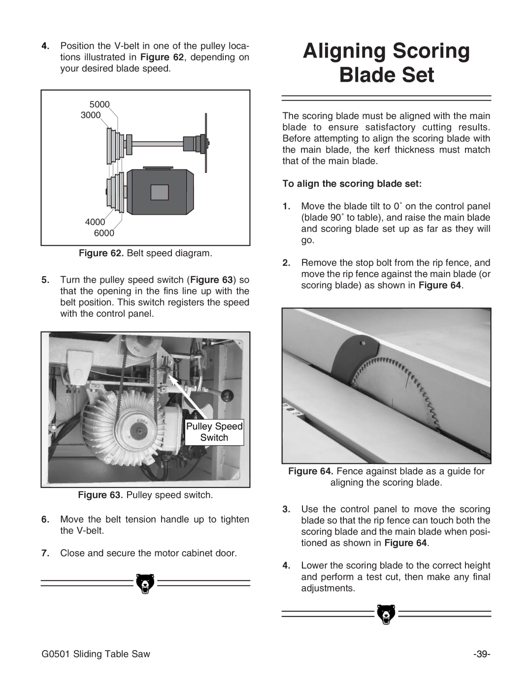
Figure 62. Belt speed diagram.
5.Turn the pulley speed switch (Figure 63) so that the opening in the fins line up with the belt position. This switch registers the speed with the control panel.
Pulley Speed
Switch
Figure 63. Pulley speed switch.
6.Move the belt tension handle up to tighten the V-belt.
7.Close and secure the motor cabinet door.
Aligning Scoring
Blade Set
The scoring blade must be aligned with the main blade to ensure satisfactory cutting results. Before attempting to align the scoring blade with the main blade, the kerf thickness must match that of the main blade.
To align the scoring blade set:
1.Move the blade tilt to 0˚ on the control panel (blade 90˚ to table), and raise the main blade and scoring blade set up as far as they will go.
2.Remove the stop bolt from the rip fence, and move the rip fence against the main blade (or scoring blade) as shown in Figure 64.
Figure 64. Fence against blade as a guide for
aligning the scoring blade.
3.Use the control panel to move the scoring blade so that the rip fence can touch both the scoring blade and the main blade when posi- tioned as shown in Figure 64.
4.Lower the scoring blade to the correct height and perform a test cut, then make any final adjustments.
G0501 Sliding Table Saw |
