Installing |
|
Tools Needed | Qty |
Hex Wrench 5mm | 1 |
To install cam-lock studs into a chuck or face- plate:
1.Lay the chuck or faceplate upside down on protective, flat surface.
2.If installed, remove the three locking cap screws adjacent to the
Stud
Locking Cap
Screw
Figure 27. Cam-lock stud and locking cap
screw.
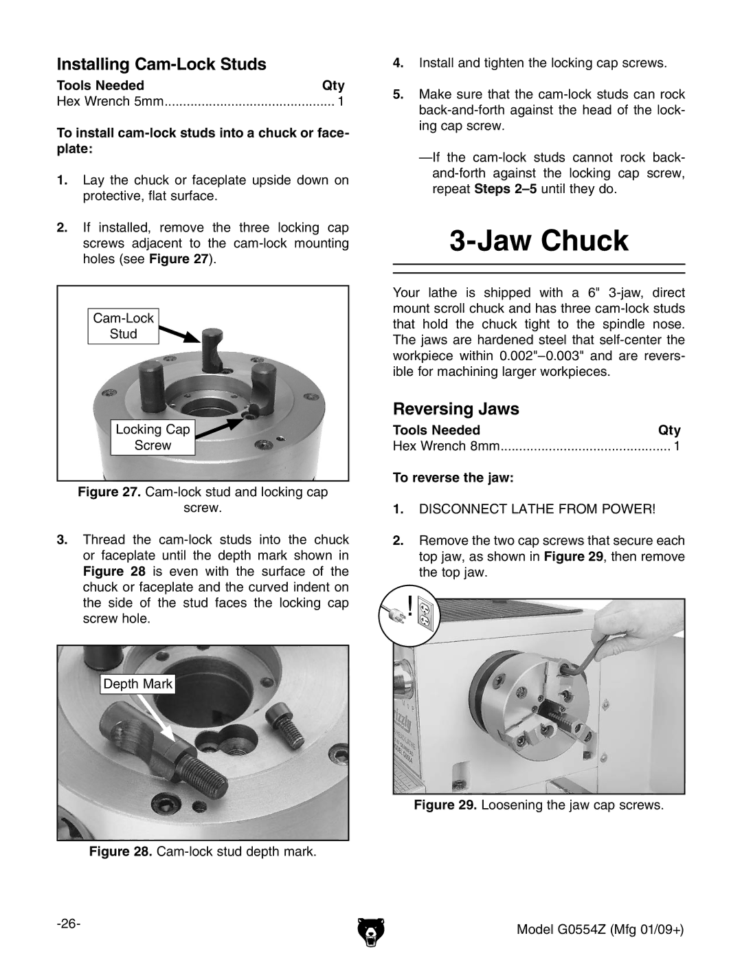
3.Thread the cam-lock studs into the chuck or faceplate until the depth mark shown in Figure 28 is even with the surface of the chuck or faceplate and the curved indent on the side of the stud faces the locking cap screw hole.
Depth Mark
Figure 28. Cam-lock stud depth mark.
4.Install and tighten the locking cap screws.
5.Make sure that the cam-lock studs can rock back-and-forth against the head of the lock- ing cap screw.
—If the cam-lock studs cannot rock back- and-forth against the locking cap screw, repeat Steps 2–5 until they do.
3-Jaw Chuck
Your lathe is shipped with a 6"
Reversing Jaws |
|
Tools Needed | Qty |
Hex Wrench 8mm | 1 |
To reverse the jaw: |
|
1.DISCONNECT LATHE FROM POWER!
2.Remove the two cap screws that secure each top jaw, as shown in Figure 29, then remove the top jaw.