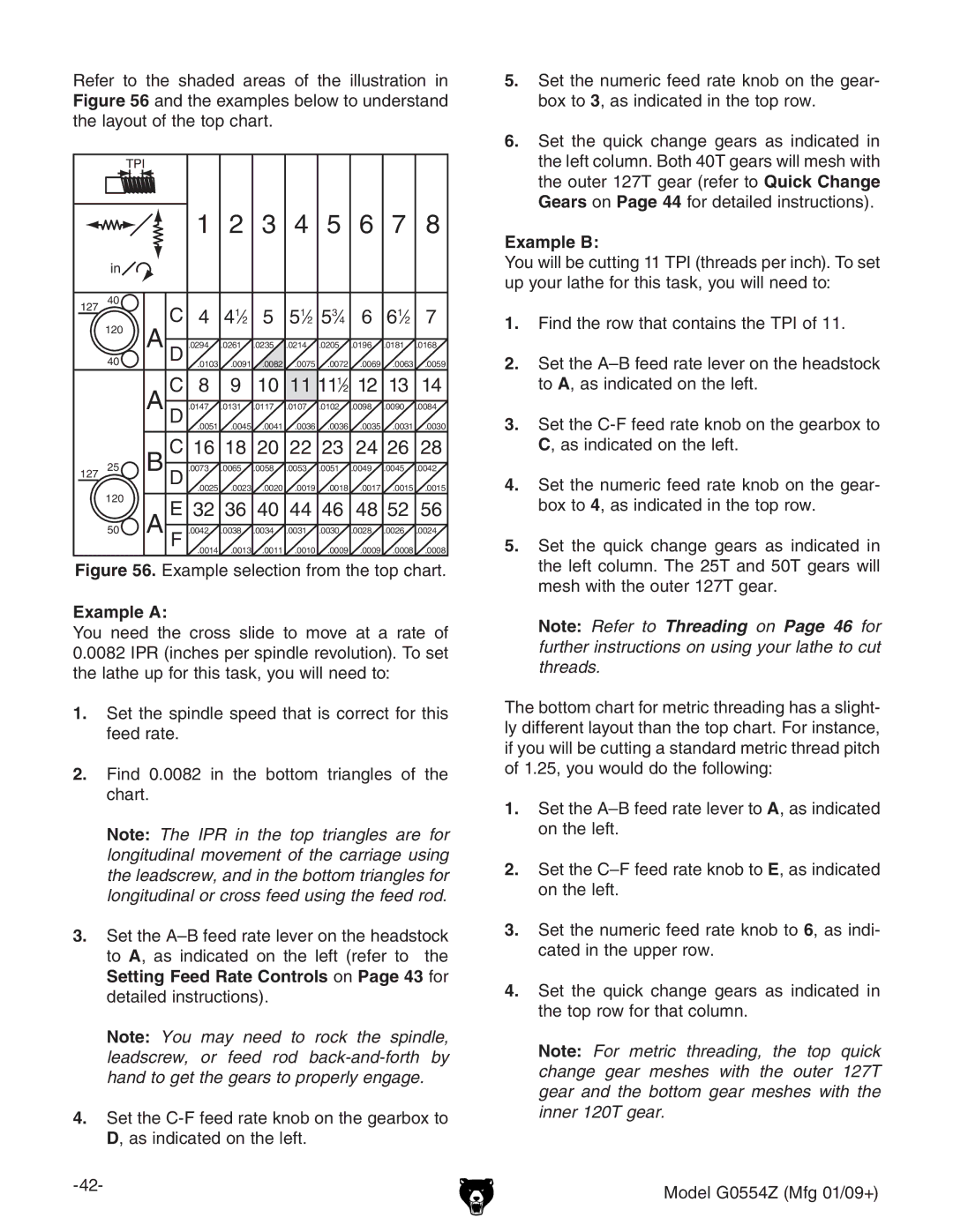
Refer to the shaded areas of the illustration in Figure 56 and the examples below to understand the layout of the top chart.
|
| TPI |
|
|
|
|
|
|
|
|
|
|
|
|
| 1 | 2 | 3 | 4 | 5 | 6 | 7 | 8 |
| in |
|
|
|
|
|
|
|
|
|
|
127 | 40 |
| C | 4 41⁄2 5 51⁄2 53⁄4 | 6 61⁄2 7 | ||||||
| 120 | A | |||||||||
| D | .0294 | .0261 | .0235 | .0214 | .0205 | .0196 | .0181 | .0168 | ||
| 40 |
| .0103 | .0091 | .0082 | .0075 | .0072 | .0069 .0063 .0059 | |||
|
|
| |||||||||
|
|
| C | 8 | 9 | 10 11 111⁄2 | 12 13 | 14 | |||
|
| A D | .0147 | .0131 | .0117 | .0107 | .0102 | .0098 | .0090 | .0084 | |
|
|
|
| .0051 | .0045 | .0041 | .0036 | .0036 | .0035 .0031 .0030 | ||
|
| B | C | 16 18 20 22 23 | 24 26 | 28 | |||||
127 | 25 | D | .0073 | .0065 | .0058 | .0053 | .0051 | .0049 | .0045 | .0042 | |
| 120 |
| .0025 | .0023 | .0020 | .0019 | .0018 | .0017 | .0015 | .0015 | |
|
| E 32 36 40 44 46 | 48 52 | 56 | |||||||
|
|
| |||||||||
| 50 | A F | .0042 | .0038 | .0034 | .0031 | .0030 | .0028 | .0026 | .0024 | |
|
|
|
| .0014 | .0013 | .0011 | .0010 | .0009 | .0009 | .0008 | .0008 |
Figure 56. Example selection from the top chart.
Example A:
You need the cross slide to move at a rate of 0.0082 IPR (inches per spindle revolution). To set the lathe up for this task, you will need to:
1.Set the spindle speed that is correct for this feed rate.
2.Find 0.0082 in the bottom triangles of the chart.
Note: The IPR in the top triangles are for longitudinal movement of the carriage using the leadscrew, and in the bottom triangles for longitudinal or cross feed using the feed rod.
3.Set the
Setting Feed Rate Controls on Page 43 for detailed instructions).
Note: You may need to rock the spindle, leadscrew, or feed rod
4.Set the
5.Set the numeric feed rate knob on the gear- box to 3, as indicated in the top row.
6.Set the quick change gears as indicated in the left column. Both 40T gears will mesh with the outer 127T gear (refer to Quick Change Gears on Page 44 for detailed instructions).
Example B:
You will be cutting 11 TPI (threads per inch). To set up your lathe for this task, you will need to:
1.Find the row that contains the TPI of 11.
2.Set the
3.Set the
4.Set the numeric feed rate knob on the gear- box to 4, as indicated in the top row.
5.Set the quick change gears as indicated in the left column. The 25T and 50T gears will mesh with the outer 127T gear.
Note: Refer to Threading on Page 46 for further instructions on using your lathe to cut threads.
The bottom chart for metric threading has a slight- ly different layout than the top chart. For instance, if you will be cutting a standard metric thread pitch of 1.25, you would do the following:
1.Set the
2.Set the
3.Set the numeric feed rate knob to 6, as indi- cated in the upper row.
4.Set the quick change gears as indicated in the top row for that column.
Note: For metric threading, the top quick change gear meshes with the outer 127T gear and the bottom gear meshes with the inner 120T gear.
Model G0554Z (Mfg 01/09+)