Grizzly G0554Z Threading Controls, Power Feed Lever, Half-Nut Lever, Thread Dial & Chart

Models: G0554Z

1 104
Download 104 pages 3.24 Kb
Page 48
Image 48

Threading Controls

The purpose of this subsection is to orient you with the controls used when threading and how to use the threading dial.

If you are unfamiliar with threading on a lathe, we strongly recommend that you read books, review industry trade magazines, or get formal training before beginning any threading projects.

Power Feed Lever

The power feed lever must be in the disengaged (horizontal) position for threading operations or the
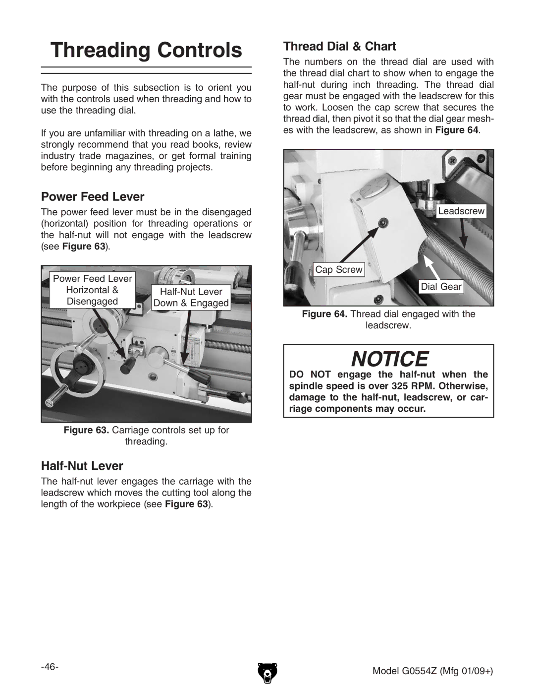
 half-nut will not engage with the leadscrew (see Figure 63).

Power Feed Lever


Horizontal &

Half-Nut Lever

Disengaged

Down & Engaged

Figure 63. Carriage controls set up for

threading.

Half-Nut Lever

The half-nut lever engages the carriage with the leadscrew which moves the cutting tool along the length of the workpiece (see Figure 63).

Thread Dial & Chart

The numbers on the thread dial are used with the thread dial chart to show when to engage the half-nut during inch threading. The thread dial gear must be engaged with the leadscrew for this to work. Loosen the cap screw that secures the thread dial, then pivot it so that the dial gear mesh- es with the leadscrew, as shown in Figure 64.

Leadscrew

Cap Screw

Dial Gear

Figure 64. Thread dial engaged with the

leadscrew.

NOTICE

DO NOT engage the half-nut when the spindle speed is over 325 RPM. Otherwise, damage to the half-nut, leadscrew, or car- riage components may occur.

-46-

Model G0554Z (Mfg 01/09+)


Page 48
Image 48
Grizzly G0554Z owner manual Threading Controls, Power Feed Lever, Half-Nut Lever, Thread Dial & Chart