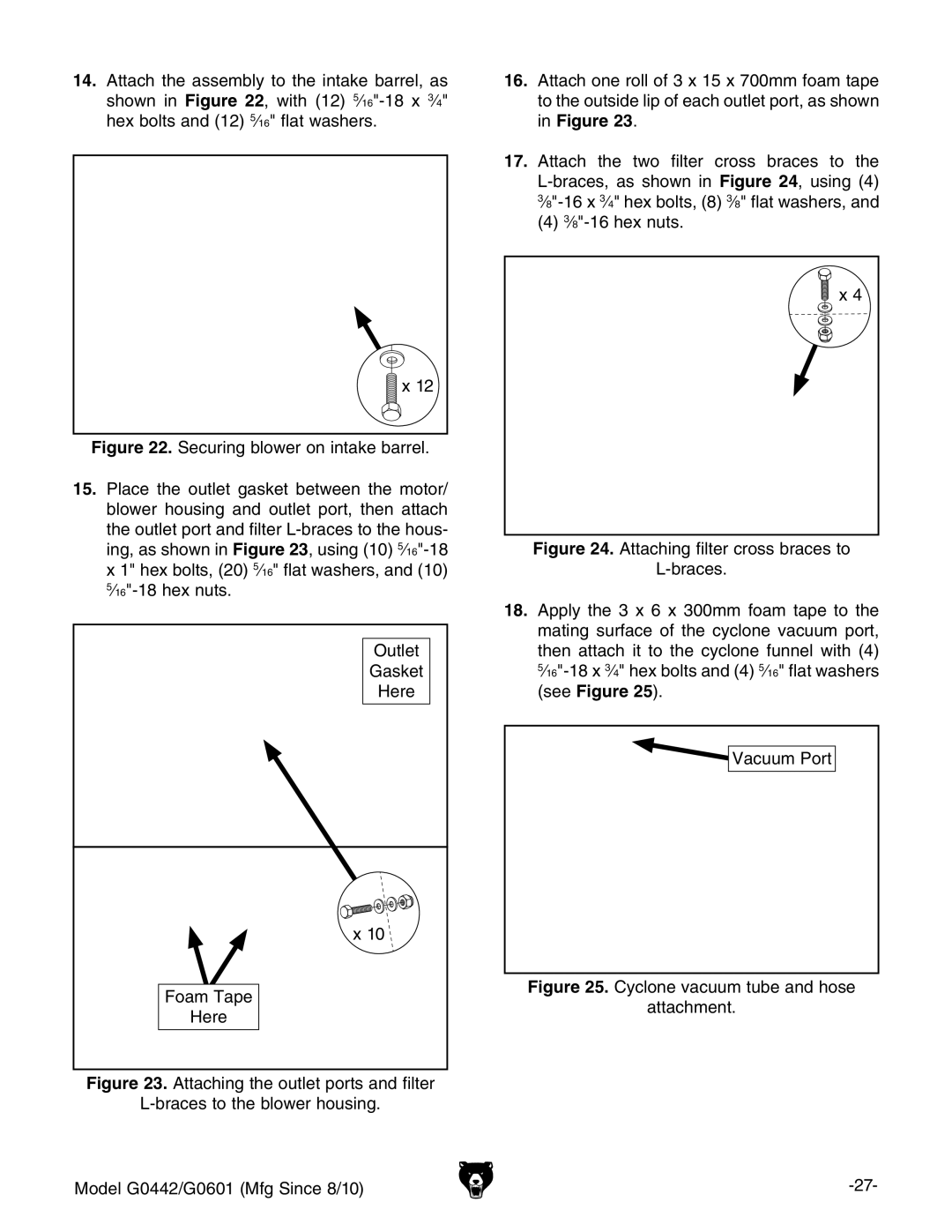
14.Attach the assembly to the intake barrel, as shown in Figure 22, with (12)
![]() x 12
x 12
Figure 22. Securing blower on intake barrel.
15.Place the outlet gasket between the motor/ blower housing and outlet port, then attach the outlet port and filter L-braces to the hous- ing, as shown in Figure 23, using (10) 5⁄16"-18 x 1" hex bolts, (20) 5⁄16" flat washers, and (10) 5⁄16"-18 hex nuts.
Outlet
Gasket
Here
x 10
Foam Tape
Here
Figure 23. Attaching the outlet ports and filter
L-braces to the blower housing.
Model G0442/G0601 (Mfg Since 8/10)
16.Attach one roll of 3 x 15 x 700mm foam tape to the outside lip of each outlet port, as shown in Figure 23.
17.Attach the two filter cross braces to the L-braces, as shown in Figure 24, using (4) 3⁄8"-16 x 3⁄4" hex bolts, (8) 3⁄8" flat washers, and
(4)3⁄8"-16 hex nuts.
![]() x 4
x 4
