BAD |
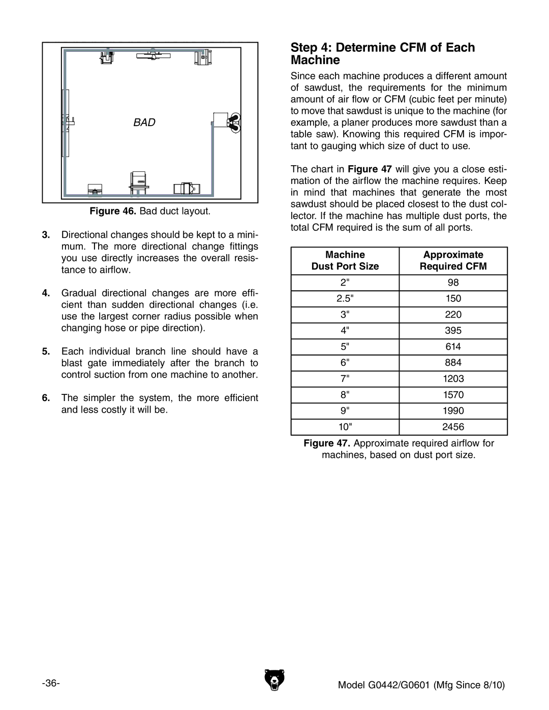
Figure 46. Bad duct layout.
3.Directional changes should be kept to a mini- mum. The more directional change fittings you use directly increases the overall resis- tance to airflow.
4.Gradual directional changes are more effi- cient than sudden directional changes (i.e. use the largest corner radius possible when changing hose or pipe direction).
5.Each individual branch line should have a blast gate immediately after the branch to control suction from one machine to another.
6.The simpler the system, the more efficient and less costly it will be.
Step 4: Determine CFM of Each Machine
Since each machine produces a different amount of sawdust, the requirements for the minimum amount of air flow or CFM (cubic feet per minute) to move that sawdust is unique to the machine (for example, a planer produces more sawdust than a table saw). Knowing this required CFM is impor- tant to gauging which size of duct to use.
The chart in Figure 47 will give you a close esti- mation of the airflow the machine requires. Keep in mind that machines that generate the most sawdust should be placed closest to the dust col- lector. If the machine has multiple dust ports, the total CFM required is the sum of all ports.
Machine | Approximate |
Dust Port Size | Required CFM |
|
|
2" | 98 |
|
|
2.5" | 150 |
|
|
3" | 220 |
|
|
4" | 395 |
|
|
5" | 614 |
|
|
6" | 884 |
|
|
7" | 1203 |
|
|
8" | 1570 |
|
|
9" | 1990 |
|
|
10" | 2456 |
|
|
Figure 47. Approximate required airflow for
machines, based on dust port size.
Model G0442/G0601 (Mfg Since 8/10) |