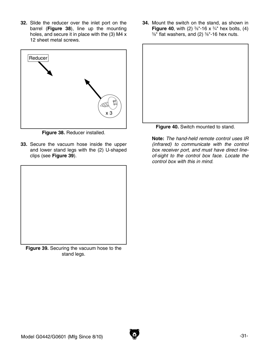
32.Slide the reducer over the inlet port on the barrel (Figure 38), line up the mounting holes, and secure it in place with the (3) M4 x 12 sheet metal screws.
Reducer
x 3
Figure 38. Reducer installed.
33.Secure the vacuum hose inside the upper and lower stand legs with the (2) U-shaped clips (see Figure 39).
Figure 39. Securing the vacuum hose to the
stand legs.
34.Mount the switch on the stand, as shown in Figure 40, with (2) 3⁄8"-16 x 3⁄4" hex bolts, (4) 3⁄8" flat washers, and (2) 3⁄8"-16 hex nuts.
Figure 40. Switch mounted to stand.
Note: The
Model G0442/G0601 (Mfg Since 8/10) |