2.Read and follow the safety instructions at the beginning of the manual, take all required safety precautions, and make sure all pre- vious preparation steps discussed in this manual have been followed and completed.
3.Clear away all tools and objects used during assembly, lubrication, and preparation.
4.Make sure that the chuck and jaws, if installed, are secure.
Note: If a chuck is not installed on the lathe, you do not need to install one for this test.
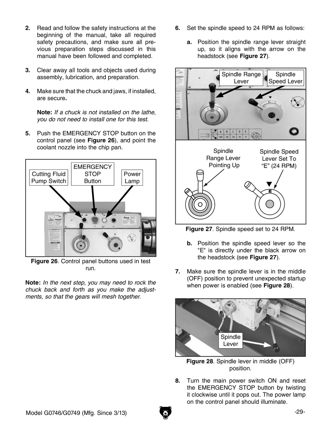
5.push the EMERGENCY STOP button on the control panel (see Figure 26), and point the coolant nozzle into the chip pan.
| EMERGENCY |
|
Cutting Fluid | STOP | Power |
Pump Switch | Button | Lamp |
Figure 26. Control panel buttons used in test
run.
Note: In the next step, you may need to rock the chuck back and forth as you make the adjust- ments, so that the gears will mesh together.
Model G0746/G0749 (Mfg. Since 3/13)
6.Set the spindle speed to 24 RPM as follows:
a.Position the spindle range lever straight up, so it aligns with the arrow on the headstock (see Figure 27).
Spindle Range | Spindle | |
Lever |
| Speed Lever |
Spindle | Spindle Speed | |
Range Lever |
| Lever Set To |
Pointing Up |
| “E” (24 RPM) |
|
| E |
Figure 27. Spindle speed set to 24 RPM.
b.Position the spindle speed lever so the "E" is directly under the black arrow on the headstock (see Figure 27).
7.Make sure the spindle lever is in the middle (OFF) position to prevent unexpected startup when power is enabled (see Figure 28).
Spindle
