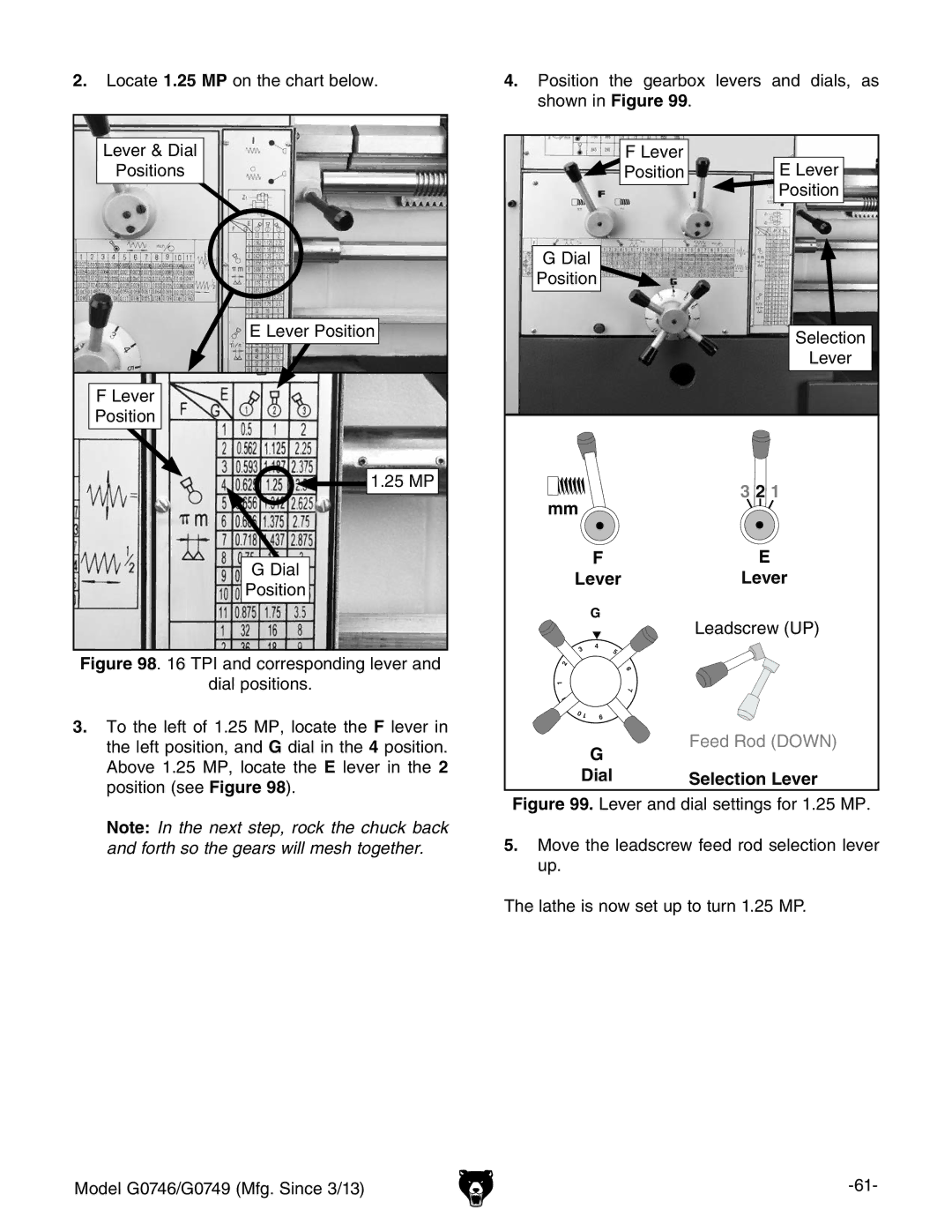
2.Locate 1.25 MP on the chart below.
Lever & Dial |
Positions |
E Lever Position |
F Lever |
Position |
1.25 MP |
G Dial |
Position |
Figure 98. 16 TPI and corresponding lever and
dial positions.
3.to the left of 1.25 MP, locate the F lever in the left position, and G dial in the 4 position. Above 1.25 MP, locate the E lever in the 2 position (see Figure 98).
Note: In the next step, rock the chuck back and forth so the gears will mesh together.
4.Position the gearbox levers and dials, as shown in Figure 99.
|
|
| F Lever | E Lever |
|
|
| Position | |
|
|
|
| Position |
G Dial |
|
| ||
Position |
|
| ||
|
|
|
| Selection |
|
|
|
| Lever |
mm |
|
| ˶ | 3 2 1 |
|
|
| ||
|
| F |
| E |
Lever |
| Lever | ||
|
| G |
| Leadscrew (UP) |
|
|
|
| |
3 |
| 4 |
|
|
| 5 |
|
| |
|
|
|
| |
2 |
|
| 6 |
|
1 |
|
|
|
|
|
|
| 7 |
|
1 |
|
|
|
|
1 |
| 8 |
|
|
|
|
|
| |
0 | 1 | 9 |
|
|
|
|
| ||
|
| G |
| Feed Rod (DOWN) |
|
|
|
| |
Dial |
| Selection Lever | ||
Figure 99. Lever and dial settings for 1.25 MP.
5.Move the leadscrew feed rod selection lever up.
The lathe is now set up to turn 1.25 MP.
Model G0746/G0749 (Mfg. Since 3/13) |
