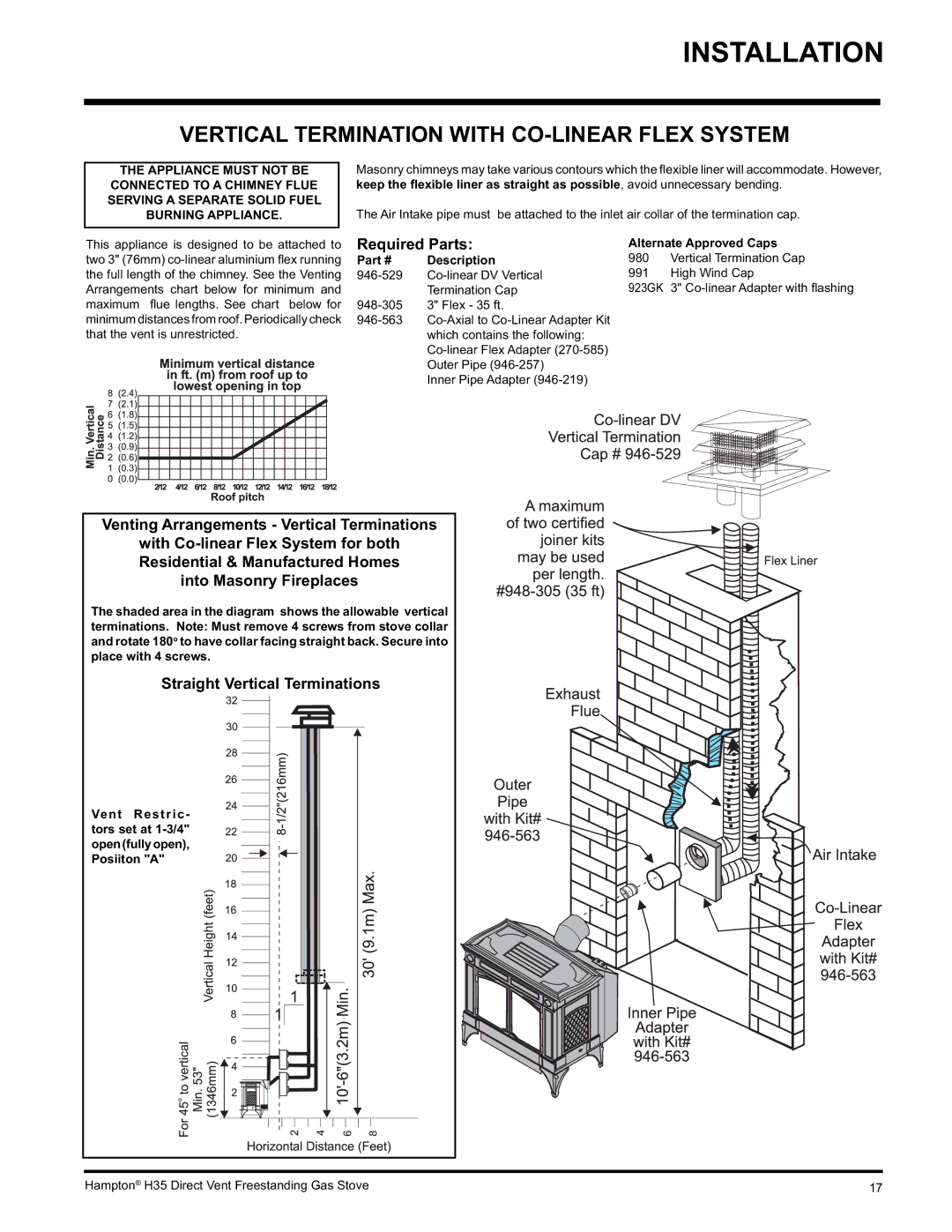
H35-NG1, H35-LP1 specifications
Hampton Direct has made significant strides in the home heating sector with its innovative products, particularly the H35-NG1 and H35-LP1 models. Both are designed to provide efficient heating solutions suitable for various residential settings.The H35-NG1 is a natural gas unit, while the H35-LP1 runs on liquid propane, allowing homeowners to choose based on their available energy resources. One of the standout features of both models is their compact design, making them ideal for small spaces or rooms where traditional heaters would be impractical.
Another key characteristic is the user-friendly digital thermostat that comes with each unit. This feature allows homeowners to easily set and adjust their desired temperature, ensuring optimal comfort throughout the day while also promoting energy efficiency. The systems are equipped with smart technology that monitors usage patterns, helping homeowners make informed decisions about their heating needs.
Safety is also at the forefront of Hampton Direct's design. Both models include advanced safety features such as an automatic shut-off mechanism to prevent overheating and a fault detection system that alerts users to any issues. This commitment to safety provides peace of mind for homeowners as they enjoy the warmth provided by these heaters.
Additionally, both the H35-NG1 and H35-LP1 are engineered to minimize noise, ensuring a quiet operation that won't disrupt daily activities. This is particularly beneficial for bedrooms or living areas where a peaceful environment is desired.
The energy efficiency rating of these units is impressive, aligning with modern environmental standards. Homeowners can expect lower utility bills and a reduced carbon footprint as both heaters efficiently convert fuel into heat.
With robust construction materials designed to withstand high temperatures, both models promise durability and longevity with minimal maintenance required. This reliability ensures that consumers will not face frequent replacements, making the H35-NG1 and H35-LP1 sound investments for any home.
In summary, Hampton Direct's H35-NG1 and H35-LP1 models deliver effective and safe heating solutions with an emphasis on energy efficiency, user-friendliness, and quiet operation. Homeowners looking for a dependable heating system will find that these models embody quality and innovation, setting new standards in the home heating industry.

