CCD OPERATION AND BAR CODE SCANNING A
A.1 Objectives
This appendix describes:
•Reading and decoding a bar code symbol.
•Overview of how the SCANTEAM 3700 works, including a scanner diagram with the main decoding elements listed.
•
•Bar code basics and scanning tips.
A.2 Scanning and Decoding a Bar Code Symbol
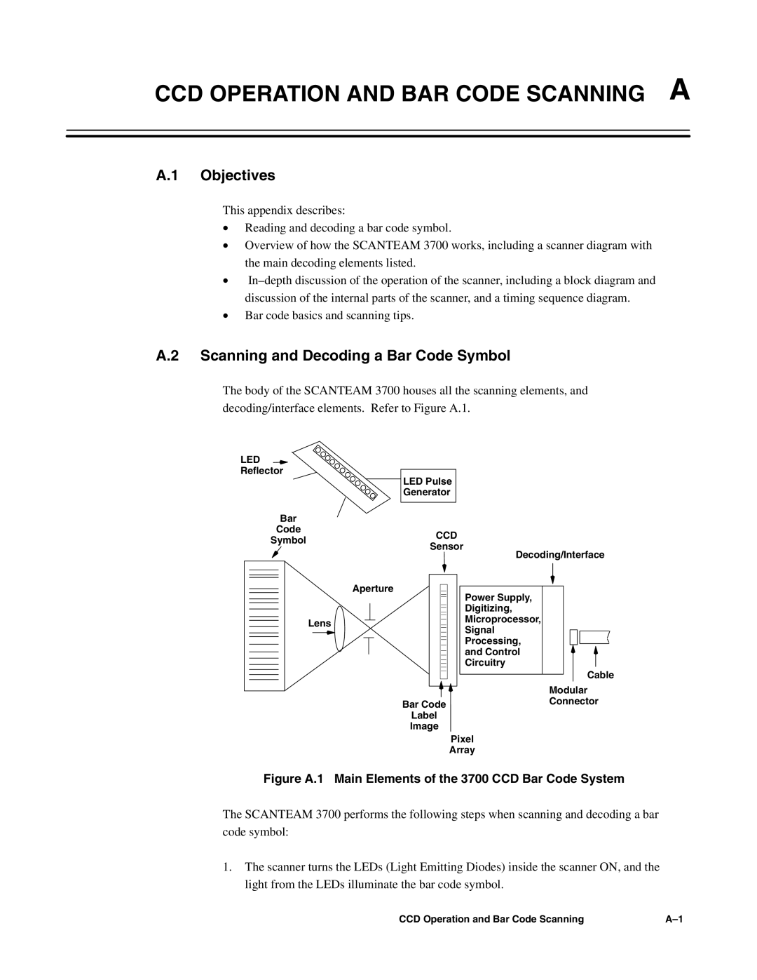
The body of the SCANTEAM 3700 houses all the scanning elements, and decoding/interface elements. Refer to Figure A.1.
LED
Reflector
LED Pulse
Generator
Bar
Code
SymbolCCD
Sensor
Decoding/Interface
| Aperture |
| Power Supply, |
|
| ||
|
|
| |
|
|
| |
|
|
| Digitizing, |
|
|
| |
|
|
| |
Lens |
|
| Microprocessor, |
|
| ||
|
| ||
|
| Signal | |
|
|
| |
|
|
| |
|
|
| Processing, |
|
|
| |
|
|
| and Control |
|
|
| |
|
|
| Circuitry |
|
|
| |
|
|
|
Cable
Modular
Bar CodeConnector
Label
Image
Pixel
Array
Figure A.1 Main Elements of the 3700 CCD Bar Code System
The SCANTEAM 3700 performs the following steps when scanning and decoding a bar code symbol:
1.The scanner turns the LEDs (Light Emitting Diodes) inside the scanner ON, and the light from the LEDs illuminate the bar code symbol.
CCD Operation and Bar Code Scanning |
