SCANTEAMR3700 CCD
Disclaimer
Patents
Page
Table of Contents
Chapter Configuring the Scanteam
CCD Operation and Bar Code Scanning
Technical Specifications
Serial Commands Summary
Ascii Conversion Table
List of Tables
Overview of the Technical Manual
Preface
Intended Audience
Related Publications
Scanteam 3700 Hardware Description
Scanteam 3700 Description
Introduction
Nonvolatile Memory
Scanteam 3700 Software Description
Interface Port
System Hardware Description
Basic System Operation
General Characteristics
Mechanical Layout
Operating Theory
Single Modular Input /Output/Power Port
Audible Indicator
Mounting Inserts
Asynchronous Serial Ascii Interface
Scanner/Host Communication
Communications Port
Hardwire Pinouts
Auxiliary Trigger
Power Requirements
SET-UP and Installation
General Preparation for Use
Preparation
Set-up Procedure for Evaluation
Set-up Checklist
Set-up Procedure
To setup serial communications to the scanner
Installation in the Host Instrument
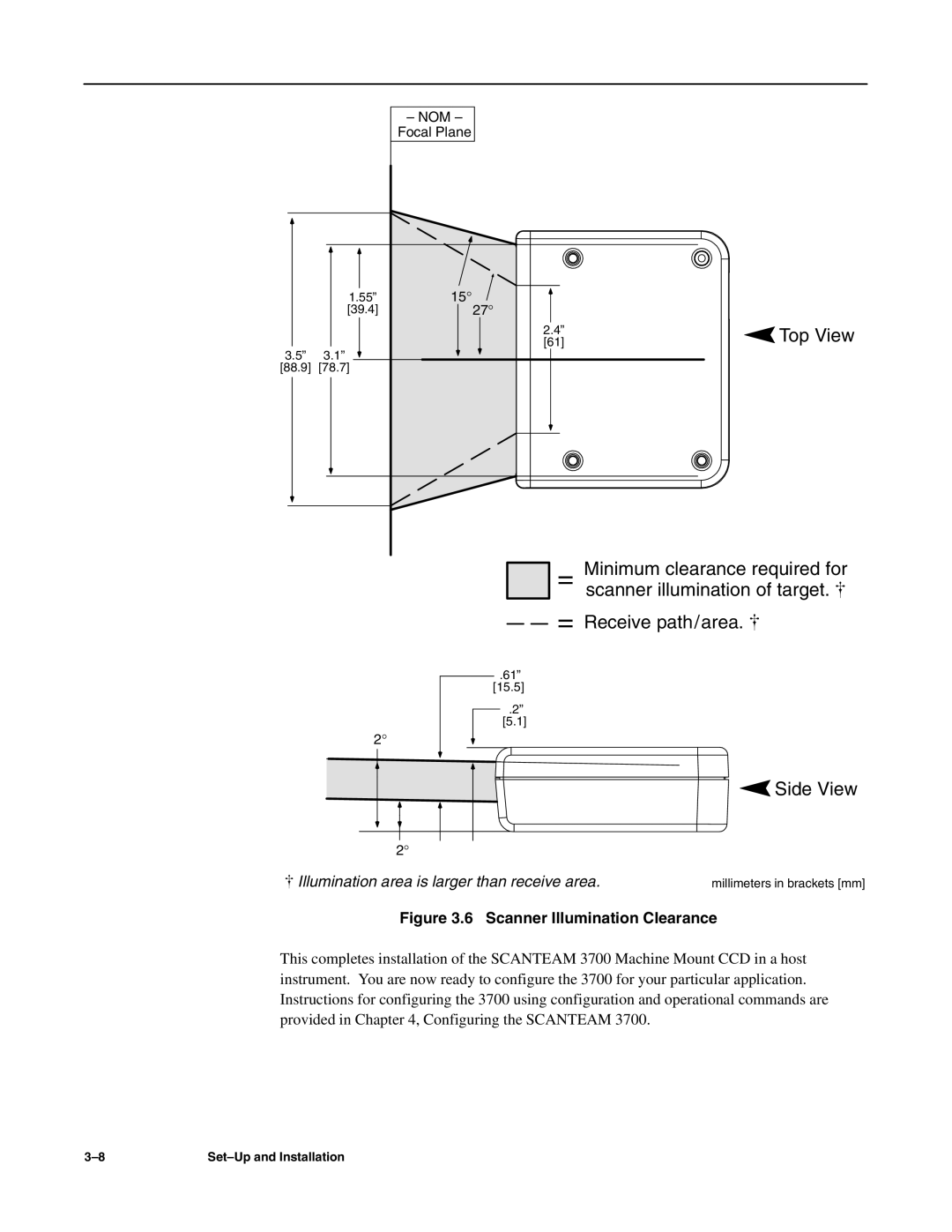
Top View
Examples of Scanteam 3700 Barcode Orientation
Pitch or Roll
Scanner Illumination Clearance
Configuring the Scanteam
Preparation
Data string
Command Conventions
Command Format
Disable Decoding Command DC4
Operational Commands
Reset Command a
Enable Decoding Command DC2
Save Configuration 3C 5A 3E
Serial Trigger Command
Save Configuration Command Z
Serial Trigger 3C 31 3E
Configuration Commands
Option
Set Communications Port Command Ka
Command Ka baud, parity, stop bits, data bits Parameter
Scanteam 3700 Code ID Values
Command Kd enable, data Parameter
Code ID Value Definition
Set Postamble Command Ke
Command Ke enable, data Parameter
Set Communications Protocol Command Kf
Command Kf mode Parameter
Set Read Timeout Command Kh
Set Trigger Mode Command Kg
Command Kg modeglobal, modeport1, modeport2, # Parameter
Set Votes Command Km
Set No Read Message Command Kk
Command Kk enable, data Parameter
Set Code 39 Command Kp
Set UPC A/E, EAN 8/13 Command Ks
Command Ks enable UPC, enable EAN Parameter
Set Scan Rate Command Kv
Set Code 128 Command Kt
Set Beeper Mode Command Ku
Configuration Status Query Commands
Default Configuration Symbology Settings
Default Operating Parameters
Default Configuration Settings
Troubleshooting Guide
SERVICE/TECHNICAL Assistance
Maintenance
Troubleshooting Hints
Problem Possible Cause Solution
Diagnostic Procedure
Troubleshooting Checklist
Scanteam 3700 Troubleshooting Checklist
Obtaining Factory Service
Product Service Department
Help Desk
Service Under Warranty
Out Of Warranty Service
Scanteam 3700 Removal/Replacement
Followed during installation Chapter
Service/Technical Assistance
Objectives
Scanning and Decoding a Bar Code Symbol
CCD Operation and BAR Code Scanning a
Peak Detectors and Comparator
LED Reflector
CCD Sensor
Microprocessor
Timing Sequence
Bar Code Scanning
Closer Look At Bar Code Symbols
Bar Code Basics and Scanning Tips
Scanner Performance
Technical Specifications
Optical Specifications
Pitch Angle
MRD minimum reflective difference 37.5%
Skew Angle
Light Source Illumination
Electrical Specifications
Environmental Specifications
Mechanical Specifications
Bar Code Symbol Specifications
Scanteam 3700 Interface Cable
To Host System
Serial Commands Summary
Command Format
Ka?
CommandFormat
Individual Configuration Query
Kd?
Symbology Configuration Default Settings
Default Configuration Settings
Configuration CommandDefault Settings
Serial Commands Summary
Ascii Conversion Table
Control Function Definitions
Ascii Conversion Table
Scanteam 3700 Glossary
Glossary-2
Glossary-3
Glossary-4
Glossary-5
Glossary-6
Index
Scanteam
Index-3
Index-4
Scanteam 3700 Limited Warranty
Jordan Road Box Skaneateles Falls, New York 3700/TM Rev E