2.2.2Single Modular Input /Output/Power Port
The interface port is an
2.2.3Audible Indicator
The beeper can be disabled by using a configuration command. Refer to Chapter 4 for information on setting configuration commands. The beeper also sounds on
2.2.4Mounting Inserts
Inserts are molded into the housing to retain mounting screws. Inserts are available for metric (3.5) or SAE
2.3Operating Theory
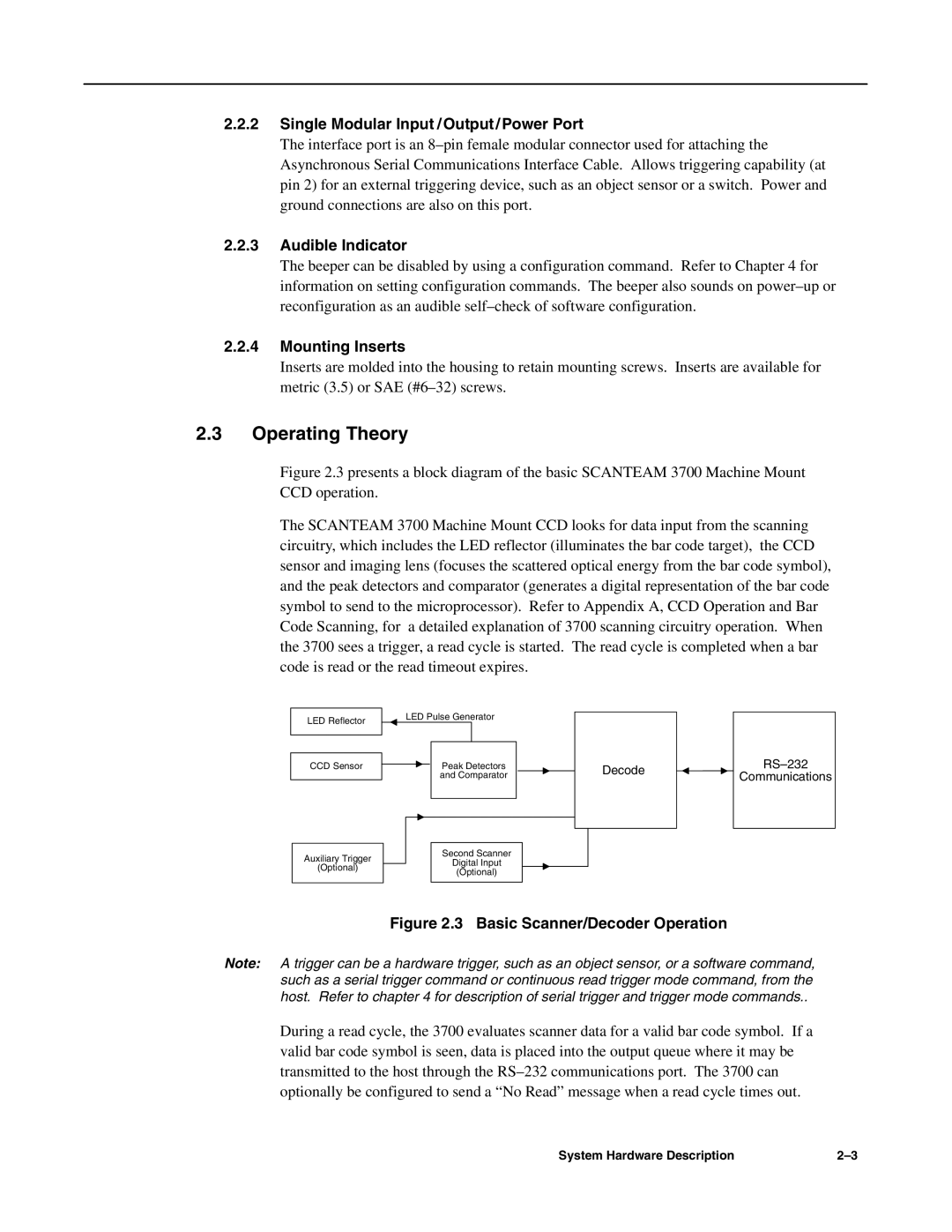
Figure 2.3 presents a block diagram of the basic SCANTEAM 3700 Machine Mount CCD operation.
The SCANTEAM 3700 Machine Mount CCD looks for data input from the scanning circuitry, which includes the LED reflector (illuminates the bar code target), the CCD sensor and imaging lens (focuses the scattered optical energy from the bar code symbol), and the peak detectors and comparator (generates a digital representation of the bar code symbol to send to the microprocessor). Refer to Appendix A, CCD Operation and Bar Code Scanning, for a detailed explanation of 3700 scanning circuitry operation. When the 3700 sees a trigger, a read cycle is started. The read cycle is completed when a bar code is read or the read timeout expires.
LED Reflector
CCD Sensor
LED Pulse Generator
Peak Detectors
and Comparator
Decode
Communications
Auxiliary Trigger
(Optional)
Second Scanner
Digital Input
(Optional)
Figure 2.3 Basic Scanner/Decoder Operation
Note: A trigger can be a hardware trigger, such as an object sensor, or a software command, such as a serial trigger command or continuous read trigger mode command, from the host. Refer to chapter 4 for description of serial trigger and trigger mode commands..
During a read cycle, the 3700 evaluates scanner data for a valid bar code symbol. If a valid bar code symbol is seen, data is placed into the output queue where it may be transmitted to the host through the
System Hardware Description |