21
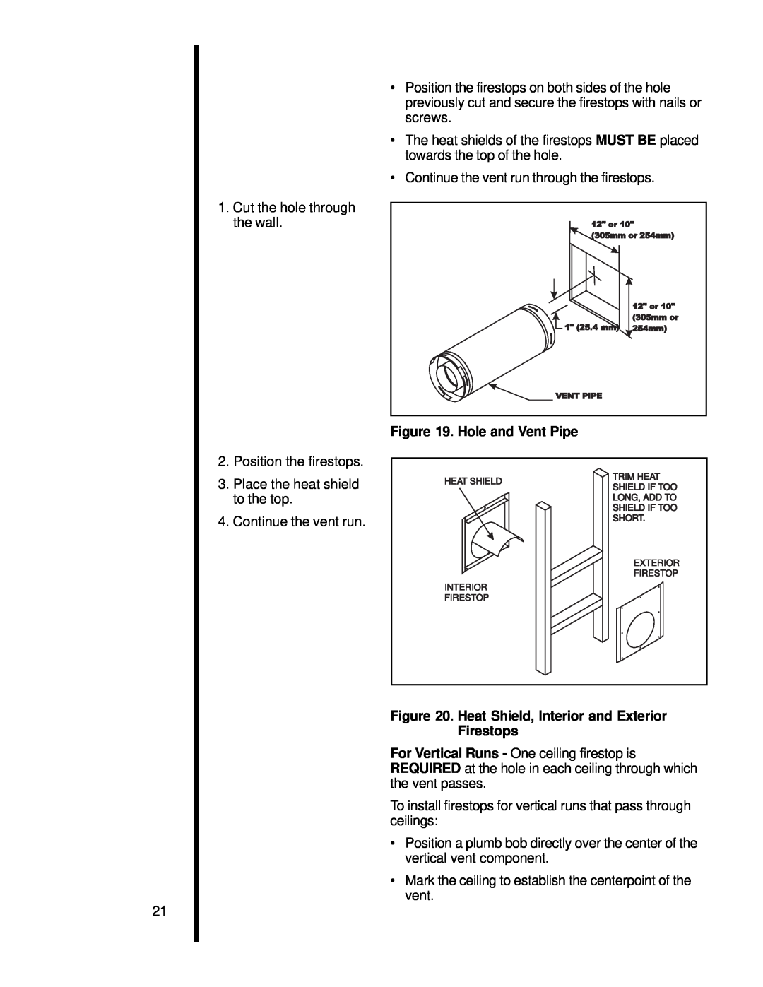
1.Cut the hole through the wall.
2.Position the firestops.
3.Place the heat shield to the top.
4.Continue the vent run.
•Position the firestops on both sides of the hole previously cut and secure the firestops with nails or screws.
•The heat shields of the firestops MUST BE placed towards the top of the hole.
•Continue the vent run through the firestops.
Figure 19. Hole and Vent Pipe
HEAT SHIELD | TRIM HEAT | |
SHIELD IF TOO | ||
| ||
| LONG, ADD TO | |
| SHIELD IF TOO | |
| SHORT. | |
| EXTERIOR | |
| FIRESTOP | |
INTERIOR |
| |
FIRESTOP |
|
Figure 20. Heat Shield, Interior and Exterior Firestops
For Vertical Runs - One ceiling firestop is REQUIRED at the hole in each ceiling through which the vent passes.
To install firestops for vertical runs that pass through ceilings:
•Position a plumb bob directly over the center of the vertical vent component.
•Mark the ceiling to establish the centerpoint of the vent.