Minimum Clearances from the Vent Pipe to
Combustible Materials
|
|
| For Vertical |
|
|
|
For Horizontal Sections | Sections | At Wall Firestops | ||||
|
|
|
|
|
|
|
Top | Bottom | Sides |
| Top | Bottom | Sides |
|
|
|
|
|
|
|
3 inches | 1 inch | 1 inch | 1 inch | 1/2 inch | 1 inch | |
(75 mm) | (25 mm) | (25 mm) | (25 mm) | (63.7 mm) | (13 mm) | (25 mm) |
|
|
|
|
|
|
|
|
|
|
|
|
|
|
Step 2
Framing the
Fireplace
For minimum clearances, see the direct vent termination clearance diagrams on pages 25 and 27 in this section.
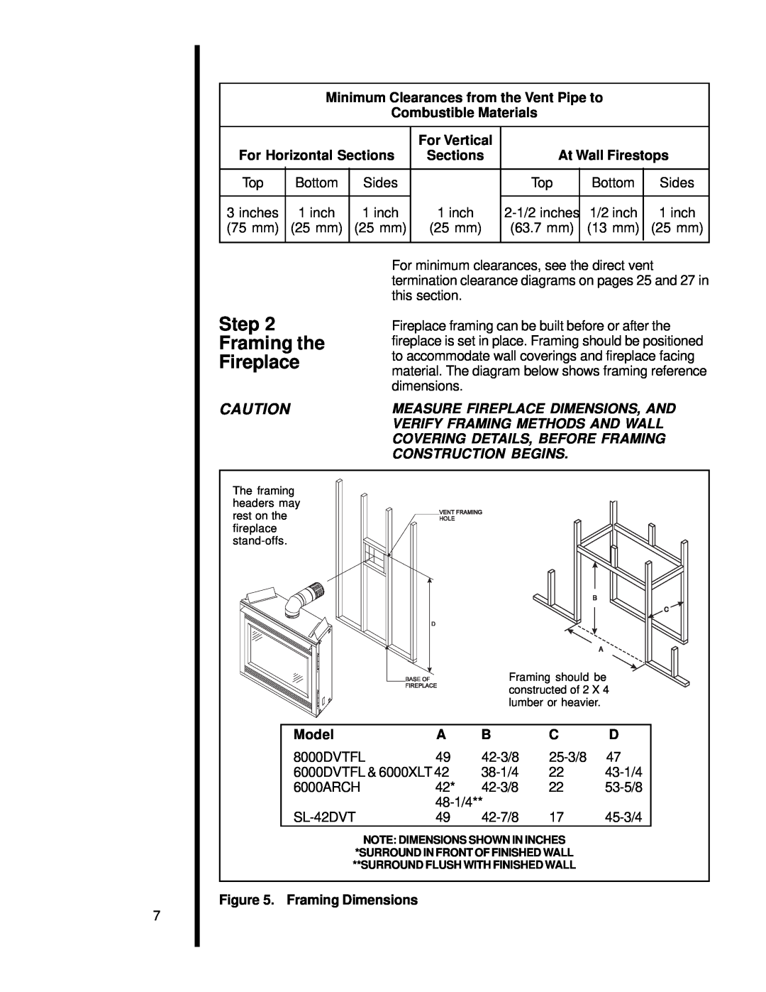
Fireplace framing can be built before or after the fireplace is set in place. Framing should be positioned to accommodate wall coverings and fireplace facing material. The diagram below shows framing reference dimensions.
7
CAUTION | MEASURE FIREPLACE DIMENSIONS, AND |
| VERIFY FRAMING METHODS AND WALL |
| COVERING DETAILS, BEFORE FRAMING |
| CONSTRUCTION BEGINS. |
The framing headers may rest on the fireplace
|
|
| B |
|
|
|
|
| C |
|
|
| A |
|
|
| Framing should be | ||
|
| constructed of 2 X 4 | ||
|
| lumber or heavier. |
| |
Model | A | B | C | D |
8000DVTFL | 49 | 47 | ||
6000DVTFL & 6000XLT 42 | 22 | |||
6000ARCH | 42* | 22 | ||
|
|
| ||
49 | 17 | |||
NOTE: DIMENSIONS SHOWN IN INCHES *SURROUND IN FRONT OF FINISHED WALL **SURROUND FLUSH WITH FINISHED WALL
Figure 5. Framing Dimensions