Heat & Glo LifeStyle 6000 XLT manual Step Gas Pressure Requirements, Gas Supply Line, Natural Gas

Models: 8000 DVTFL 6000 XLT 6000 ARCH 6000 DVTFL SL-42 DVT

1 46
Download 46 pages 22.06 Kb
Page 33
Image 33
Step 7

The gas line should be installed by a qualified service technician.

Step 7

Gas Pressure

Requirements

At the gas line access hole, use insulation to re- pack the space around the gas pipe.

Insert insulation from the outside of the fireplace and pack the insulation tightly to totally seal be- tween the pipe and the outer casing.

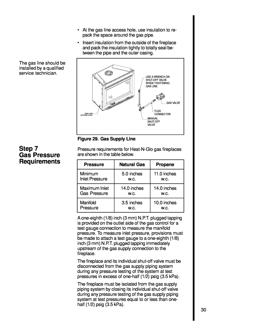
Figure 29. Gas Supply Line

Pressure requirements for Heat-N-Glo gas fireplaces are shown in the table below.

Pressure

Natural Gas

Propane


Minimum

5.0 inches

11.0 inches

Inlet Pressure

w.c.

w.c.


Maximum Inlet

14.0 inches

14.0 inches

Gas Pressure

w.c.

w.c.


Manifold

3.5 inches

10.0 inches

Pressure

w.c.

w.c.


A one-eighth (1/8) inch (3 mm) N.P.T. plugged tapping is provided on the outlet side of the gas control for a test gauge connection to measure the manifold pressure. To measure inlet pressure, provisions must be made to attach a test gauge to a one-eighth (1/8) inch (3 mm) N.P.T. plugged tapping immediately upstream of the gas supply connection to the fireplace.

The fireplace and its individual shut-off valve must be disconnected from the gas supply piping system during any pressure testing of the system at test pressures in excess of one-half (1/2) psig (3.5 kPa).

The fireplace must be isolated from the gas supply piping system by closing its individual shut-off valve during any pressure testing of the gas supply piping system at test pressures equal to or less than one- half (1/2) psig (3.5 kPa).

30

Page 33
Image 33
Heat & Glo LifeStyle 6000 XLT, 8000 DVTFL, SL-42 DVT Step Gas Pressure Requirements, Gas Supply Line, Natural Gas, Propane