•Drill a hole or drive a nail through this centerpoint.
•Check the floor above for any obstructions, such as wiring or plumbing runs.
•Reposition the fireplace and vent system, if neces- sary, to accommodate the ceiling joists and/or obstructions.
•Cut an
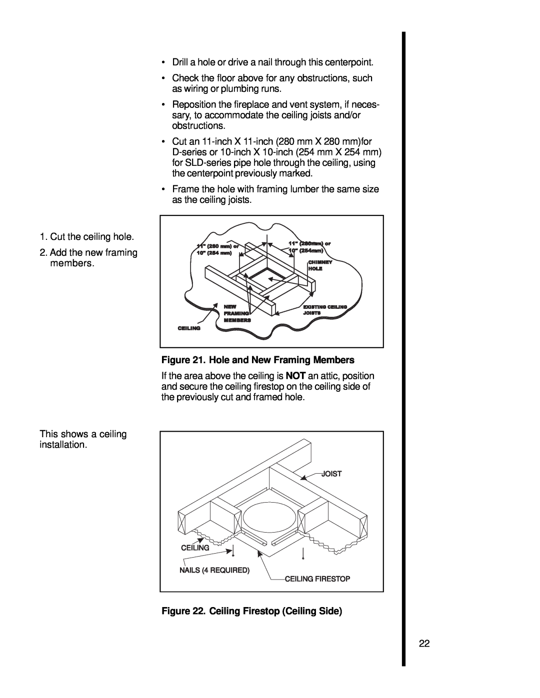
•Frame the hole with framing lumber the same size as the ceiling joists.
1. Cut the ceiling hole.
2. Add the new framing members.
Figure 21. Hole and New Framing Members
If the area above the ceiling is NOT an attic, position and secure the ceiling firestop on the ceiling side of the previously cut and framed hole.
This shows a ceiling installation.
JOIST |
CEILING |
NAILS (4 REQUIRED) |
CEILING FIRESTOP |
Figure 22. Ceiling Firestop (Ceiling Side)
22