WARNING
ENSURE THAT THE FIBERGLASS
ROPE GASKET SUPPLIED WITH THE
FIREPLACE SEALS BETWEEN THE
FIRST VENT COMPONENT AND THE
OUTER FIREPLACE WRAP.
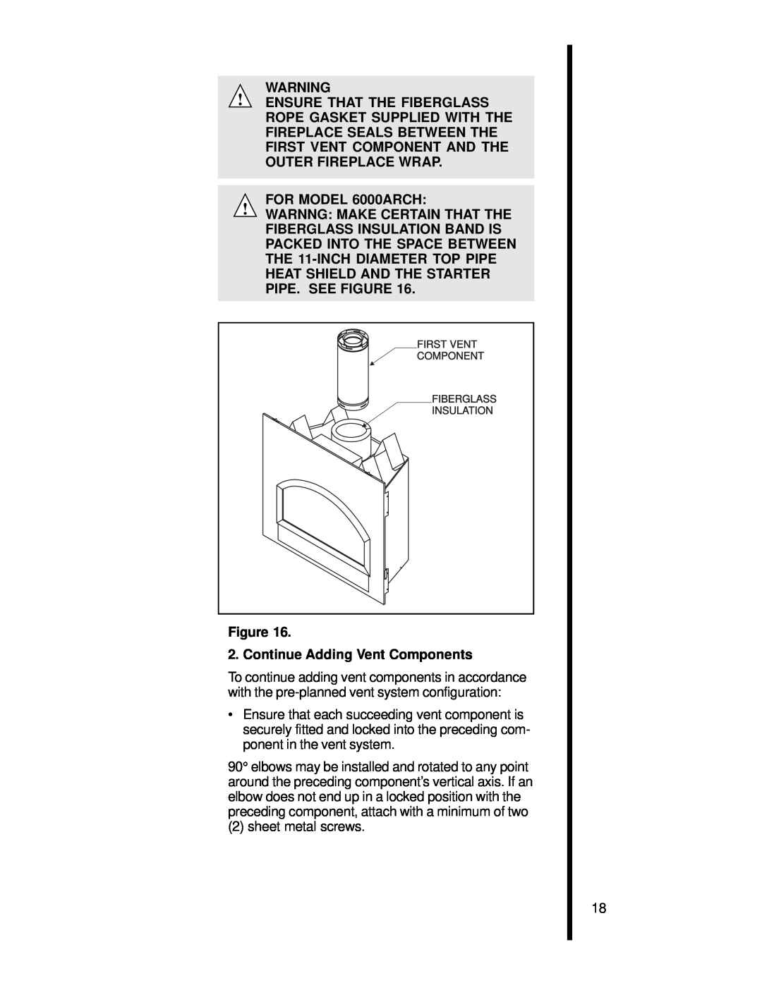
FOR MODEL 6000ARCH:
WARNNG: MAKE CERTAIN THAT THE
FIBERGLASS INSULATION BAND IS
PACKED INTO THE SPACE BETWEEN
THE
HEAT SHIELD AND THE STARTER
PIPE. SEE FIGURE 16.
FIRST VENT
![]() COMPONENT
COMPONENT
FIBERGLASS
![]() INSULATION
INSULATION
Figure 16.
2. Continue Adding Vent Components
To continue adding vent components in accordance with the
•Ensure that each succeeding vent component is securely fitted and locked into the preceding com- ponent in the vent system.
90° elbows may be installed and rotated to any point around the preceding component’s vertical axis. If an elbow does not end up in a locked position with the preceding component, attach with a minimum of two
(2) sheet metal screws.
18