Manuals
/
Heatiator
/
Household Appliance
/
Indoor Fireplace
Heatiator
GB4336
owner manual
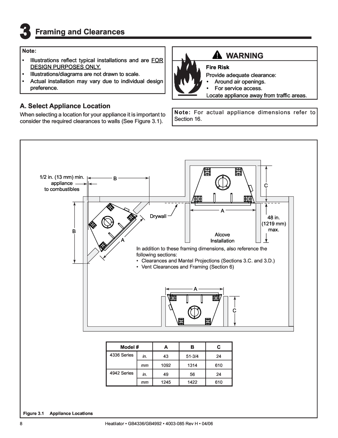
3Framing and Clearances, A. Select Appliance Location, Fire Risk
Models:
GB4336
1
8
52
52
Download
52 pages
25.36 Kb
5
6
7
8
9
10
11
12
Troubleshooting
Install
FAQ
5Vent Information and Diagrams
A. Recommendation for Wire
Warranty
Maintenance
Symptom
C. Accessories
Standing Pilot Valve Assembly
Page 8
Image 8
Page 7
Page 9
Page 8
Image 8
Page 7
Page 9
Contents
What to do if you smell gas
Models GB4336, GB4336L GB4336I, GB4336IL
GB4942, GB4942L GB4942I, GB4942IL
B-VentGas Appliance
Homeowner Reference Information
Listing Label Information/Location
Congratulations
Gas Type
Table of Contents
5 Vent Information and Diagrams
8 Installing Vent Pipe
12 Appliance Setup
D. High Altitude Installations
1Listing and Code Approvals
A. Appliance Certification
C. BTU Specifications
A. Design and Installation Considerations
2Getting Started
Asphyxiation Risk
B. Negative Pressure
Negative Pressure
Any such action may cause a fire hazard
C. Tools and Supplies Needed
D. Inspect the Appliance and Components
Fire Risk
3Framing and Clearances
A. Select Appliance Location
B. Construct the Appliance Chase
Fire Risk
C. Clearances
Fire Risk Odor Risk
D. Mantel Projections
Top of Appliance Drywall A 48 in 1219 mm B max
Mantel Leg or Perpendicular Wall A1 in. 25mm min
to perpendicular wall
Fire Risk Explosion Risk
4Termination Locations
A. Vent Termination Minimum Clearances
5Vent Information and Diagrams
A. Vent Guidelines
B. Vent System Configuration
Fire Risk Asphyxiation Risk
Vent supports
Fire Risk Explosion Risk
6Vent Clearances and Framing
A. Pipe Clearances to Combustibles
B. Wall Penetration Framing
C. Vertical Penetration Framing
A. Installing Outside Air Kit Damper Assembly
Appliance Preparation
Risk of Smoke Spillage
Fire Risk Asphyxiation Risk
B. Gas and Electrical Connections
C. Securing and Leveling Appliance
Nailing Tabs
both sides
8Installing Vent Pipe
B. Attach Vent to Firebox Assembly
A. Assemble Vent Sections
C. Securing Vent Sections
9Gas Information
A. Fuel Conversion
C. Gas Connection
B. Gas Pressure
D. High Altitude Installations
Fire Risk Explosion Risk
Gas build-upduring line purge may ignite
Fire Risk Explosion Risk Asphyxiation Risk
A. Recommendation for Wire
B. Connecting to the Appliance
C. Intellifire Ignition System Wiring
10 Electrical Information
Optional Junction Box Wiring
D. Standing Pilot Ignition System Wiring
Optional Accessories Requirements
E. Junction Box Installation
11 Finishing
A. Mantel Projections
B. Facing Material
Fire Risk
12 Appliance Setup
B. Clean the Appliance
C. Accessories
D.Install the Refractory
F. Log Removal/Replacement
I. Air Shutter Setting
G. Glass Doors
H. Hood
Fire Risk Combustion Fumes Risk
13 Operating Instructions
A. Before Lighting Appliance
Fire Risk Burn Risk HOT! DO NOT TOUCH
SEVERE BURNS MAY RESULT
C. High Limit Safety Switch
B. Check Appliance Draft
Note to Qualified Service Technician
Without
D. Lighting the Appliance
WARNING RISK OF FIRE
FOR YOUR SAFETY READ BEFORE LIGHTING
LIGHTING INSTRUCTIONS
FOR YOUR SAFETY READ BEFORE LIGHTING
NATURAL GAS
LIGHTING INSTRUCTIONS
TO TURN OFF GAS TO APPLIANCE
F. Frequently Asked Questions
E. After the Appliance is Lit
Initial Break-inProcedure
Issue
14 Troubleshooting
A. Standing Pilot Ignition System
Symptom
Possible Causes
Symptom
Possible Causes
Corrective Actions
Frequent pilot outage
B. Intellifire Ignition System
Symptom
Possible Causes
Corrective Actions
Symptom
Possible Causes
Corrective Actions
Pilot sparks, but pilot will
15 Maintaining and Servicing the Appliance
Clean
When cleaning glass door
Risk of injury or property damage
Maintenance and Service Tasks
Maintenance Tasks
Inspect
one is not present
A. Appliance Dimension Diagram
16 Reference Materials
Figure 16.1 Appliance Dimensions
Model
Service Parts
B. Service Parts List
GB4336 SERIES
Exploded Parts Diagram
Service Parts
GB4336 SERIES
Description of Part
GB4336
Standing Pilot Valve Assembly
Intermittent Pilot Valve Assembly
Service Parts
Service Parts List
Service Parts
GB4336 SERIES
Description of Part
GB4336
GB4942 SERIES
Service Parts
Exploded Parts Diagram
Beginning Manufacturing Date 1/19/04
Service Parts
GB4942 SERIES
# Description of Part
GB4942
Service Parts
Standing Pilot Valve Assembly
Intermittent Pilot Valve Assembly
Service Parts List
Service Parts
GB4942 SERIES
# Description of Part
GB4942
C. Optional Components
ID4 Insulated Duct
in. 102 mm
UD4 Uninsulated Duct 4 in. 102 mm 42 in 1067 mm
This page intentionally left blank
This page intentionally left blank
D. Limited Lifetime Warranty
Gas Appliance Fireplace Limited Lifetime Warranty
Limited Lifetime Warranty
1 Year Limited Warranty
E. Contact Information
Hearth & Home Technologies Inc
1915 W. Saunders Street Mt. Pleasant, Iowa
DO NOT DISCARD THIS MANUAL
Top
Page
Image
Contents